 The
Science Notebook
The
Science NotebookGilbert Atomic Energy - Part II
Home Terms of Use Safety Contact Us Experiment Pages Downloads Supplies Useful Links!
 The
Science Notebook
The
Science NotebookHome Terms of Use Safety Contact Us Experiment Pages Downloads Supplies Useful Links!
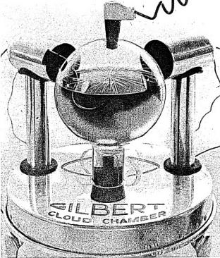
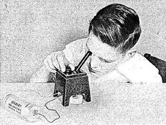
Of all the Atomic instruments, the Gilbert Cloud Chamber is the most striking in its ability to show the nature of radioactivity. You may wonder why we have waited until now to discuss its use. The reason for this is that we wanted to introduce you to gamma rays first, before going on to describe other types of rays. It happens that the Cloud Chamber will not show gamma ray tracks.
Here is how the Cloud Chamber is assembled.
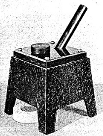
1) Lay out some newspapers or a plastic sheet on a flat table to serve as a working space. The papers will protect the furniture in case you spill any alcohol or ink. On the table place the aluminum Cloud Chamber base (the round plate with the three legs).
21
2) Fasten the rubber mounting block (with the cylindrical lip placed up wards) to the underside of the base. (See Figure 2-2.)
3) Insert the metal tubing into the rubber mounting block with the long end of the tubing up. (See Figure 2-2.)
4) To the tube projecting from the underside of the base fasten the bare end of the black lead wire and the plastic tube and rubber bulb. Make sure that all connections are tight, for they must hold liquid without leaking. (See Figure 2 -2.)
5) Place the large stopper in the neck of the glass flask. Moisten the end of the metal tubing which extends through the base and with a gentle screwing action squeeze the rubber stopper (in the pyrex flask) over the metal tube. Be sure to moisten the tube or you will find it very difficult to squeeze the flask onto the tube. Make sure that the flask now stands securely on the base and that the connection is tight. (See Figure 2-3.)
6) Now remove the stopper in the top of the flask and, using the small funnel provided with the lab, pour into the top hole of the flask approximately one pint of rubbing alcohol. Any brand of rubbing alcohol with the exception of aromatic rubbing alcohol is satisfactory. The 70% solution known as isopropyl rubbing alcohol provides the best results. One pint of alcohol should fill the chamber just to the level of the side hole in the flask.
22
7) Depress the grey rubber bulb several times to eliminate air from the system and check all connections for leaks. Alcohol may harm certain furniture finishes so care must be exercised in its use. When you depress the grey bulb alcohol may be forced above the level of the side hole; to secure against leaks at this point force the rubber stopper (this comes fixed in the flask) firmly into the hole on the side of the flask.
8) Now add a few drops of blue-black ink to the alcohol. You may do this by using a fountain pen. Insert it into the top of the flask. Enough ink should be added to color the liquid medium blue. Ordinary ink is satisfactory for this purpose.
9) Replace the stopper in the top of the chamber.
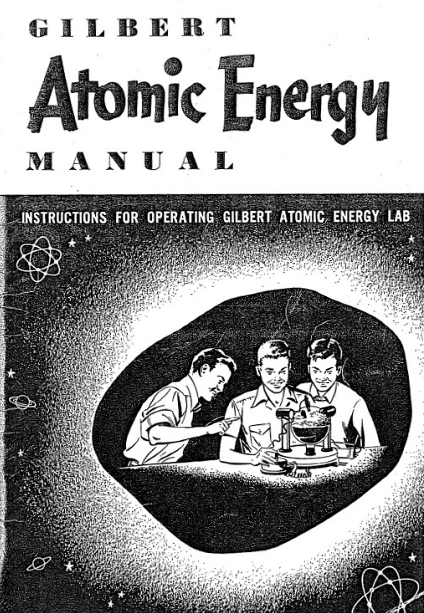
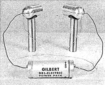
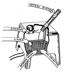
10) Assemble the lighting system as shown in the illustration. (See figure 2-1.) Take care to moisten the rubber grommets before trying to force the aluminum legs into place. Align the lights so that the center of the light housing is just about the level of the liquid. Adjust the light housings so that both lights are aimed at the center of the chamber.
11) Connect both black leads from the light housing to one terminal of the Dri-electric Power Pack. Then connect the yellow leads to the other ter-
23
minal. (See figure 2-4). Both lights should now be on and you can readjust the light beams so that the chamber is fully illuminated.
12) The only item left to be connected is the Deionizer. Plug the red lead from the Deionizer to the metal projection on the rubber plug of the of the flask. Plug the black lead from the underside of the Cloud Chamber base into the black opening on the side of the deionizer. Now plug the service plug into a house outlet and the Cloud Chamber is ready to operate.
Now that you have everything in order, squeeze the grey rubber bulb, forcing the liquid to rise in the chamber. Do this fairly slowly by pressing down on the bulb with a steady motion. Otherwise you will cause the liquid to squirt up violently and this is not desirable. A little practice will allow you to control the compression of the chamber in a steady way. We say compression because, by forcing liquid into the flask, the trapped air is forced to a smaller space and therefore it is compressed. When you release the bulb quickly, the liquid level drops and the gas expands.
1f you squeeze the rubber bulb, then wait for a moment so that the liquid is no longer in motion, and then release the bulb, you will see that a fine mist or fog fills the air space in the chamber. Observe how gracefully the fog descends. If you do not observe any fog formation make sure of two things. First, be sure that you pause after squeezing the bulb. Second, it may happen that you have not squeezed the bulb firmly enough. Try this and if after a number of attempts you still do not produce fog, it is probably because you do not have enough liquid in the chamber, Add a few ounces of alcohol to the chamber and you should. be able to produce fog.
If the two rubber stoppers at the top and side of the glass flask are so loose that air rushes out when you squeeze the bulb, you will never obtain proper operation of the instrument. To correct this, wet the stoppers and twist them firmly into the flask.
Why does fog form in the Cloud Chamber? Fog is produced in the chamber for exactly the same reason that it is produced out of doors. Tiny droplets of water condense onto invisible specks of dust. In the case of the Cloud Chamber, the expansion of the air causes cooling and the air contains so much water vapor (in invisible form) that the slightest disturbance causes this vapor to condense into small droplets of water which are then visible as fog. Very tiny particles of dirt and dust in the air will be enough disturbance for the water vapor to condense out on these tiny particles. This is what happens in the Cloud Chamber when you compress and expand it.
In the event that there are radioactive materials, such as the active wire which is in the Gilbert chamber, shooting out radiations into the gas, then there will be broken-up atoms or ions present which will also start the formation of fog. If the ions aro along a path, the fog will form along the path and make it visible, showing us where a radioactive ray has streaked across the flask a split second before. This will look something like the vapor trails which high-flying airplanes sometimes produce in a clear sky.
24
Before we set off on our experiments with cloud tracks of particles, lets see what we can learn about the fog itself. First, let us show that the particles on which the fog forms actually cannot be seen. To do this expand the chamber several times until the fog gets thinner and you can distinctly make out the swirling lines within the fog as it drops toward the surface of the liquid. Now expand the chamber, causing fog to form, and then, before the fog disappears, compress the chamber again until all of the fog vanishes. Then release the rubber bulb and note that the fog which is seen forms along the same swirling lines as before. Clearly, these invisible particles must be in the chamber when no fog is present. Our experiment catches the invisible particles and makes them visible by means of forming droplets on them
25
We can also use our chamber to make super-clean air. To do this we squeeze the bulb several times, allowing the fog to drop into the liquid after each squeezing. Little by little the fog will become thinner and after awhile no fog will form. At this time the air above the surface of the liquid will be super-clean, far cleaner than air which you may find on the clearest day.
Another trick which we can do with the chamber is to make the colors of sunrise and sunset. Everyone has at some time or other marveled at the gorgeous display of sunrise or sunset colors. These colors are even more beautiful when they appear in clouds near the horizon. The tiny droplets of water which make up the clouds scatter the rays of light and produce many hues. You can make these sunset colors on a very small scale in your Cloud Chamber. Look into the chamber so that you gaze almost directly at one of the lights, Then squeeze the bulb fully and observe the colors produced in the fog. Better results can be obtained if you use only one dry cell to power the lamps.
Fix the position of the radioactive wire by moving the rubber stopper slightly, one way or the other; make sure that the end of the wire points upward and is even with the surface of the alcohol when the bulb is squeezed. Depress and quickly release the rubber bulb several times; this will serve to clear the chamber and make ¡t ready for operation. Depress the rubber bulb. Press down the black push button on the Deionizer and hold it down a moment. Release the push button and quickly release your hold on the rubber bulb. Observe the dense white tracks which shoot out radially from the wire. (See Figure 2-5.)
Obtaining good clear tracks is done more carefully than merely making fog in the chamber. You will have to try a few times before you are proficient at making alpha tracks. Once you have fixed the position of the alpha source (the radioactive wire in the flask) so that neither too many nor too few particles shoot out into the air space of the flask, you can then change the amount of compression given to the air by squeezing the rubber bulb. By raising the end of the radioactive wire you can allow more alpha particles to escape to the air space.
Our source, the radioactive wire, shoots out about 740 alpha particles per second. Not all of these escape from the surface of the wire and many are absorbed in the liquid, so that when the chamber is expanded you see only a few of the many particles shot out in each second from the source,
If you doubt that the alpha particles really are shot out by the wire source, you can easily see that this is true by performing a very simple experiment. At this point in your experimentation, you ought to be developing an inquiring attitude with which you think about the experiments before they are written out in cook-book fashion.
When you have doubts about the statement that the alpha particles actually come from the source (radioactive wire) you should ask yourself: What facts
26
do I have to prove this point? First, you know from our experiments that the alpha tracks seem to start at the tip of the wire. Second, you know that when more of the wire is exposed, there are more alpha tracks in the flask. As a final experiment, you can completely cover the wire with liquid. When you do this all the alpha tracks should disappear from the chamber.
You may draw another conclusion from the experiment just performed. Because you allowed only a thin layer of liquid to come between the wire from the air space1 you can see that the alpha particles are easily absorbed in liquid.
It is one thing to say that alpha particles are easily absorbed in matter, and another to describe this absorption so that everyone will be able to talk about the same thing. Let us see how we might be able to define the units in which alpha absorption can be measured, in expanding your chamber and watching the tracks from alpha particles, the first thing you notice is their straightness, If we watch the alpha tracks very carefully we will see that the tracks really end in the gas of the chamber. Adjust your alpha source (radioactive wire) so that it is well above the liquid level and note that the many tracks shoot out like the spines on a porcupine and, like these spines, they are all of about the same length. Most of the tracks seem to reach to about a half inch from the wall of the glass flask. if we estimate the distance that each track covers we find it is about 1-1/2 inches.
Since all the tracks seem to have about the same length we can now adopt as our unit of measurement for alpha particle absorption the number of inches the particle travels before stopping; this distance we call the range of the alpha particle.
This experiment requires a little skill on your part, but you should be able to carry it out without too much trouble. We shall try to show that the alpha particles shot out by the radioactive wire cannot go through even a very thin sheet of aluminum foil.
To make the foil properly choose the thinnest aluminum or metallic foil which you can find and then shape it around the blunt end of a large needle so that it forms a cap which can be slipped over the tip of the radioactive wire. Make the cap about half an inch in length and gently slide it over the end of the Cloud Chamber radioactive wire. Now put it carefully back into the chamber and adjust the tip as before. Expand the chamber a number of times and see if you can note any alpha particles. No alpha particles should be able to sneak through the metallic cap. Your experiment proves that even very thin foil effectively absorbs alpha particles.
A word of caution when you are handling the Cloud Chamber alpha source in this experiment. Do not break off the tip or otherwise damage the radioactive wire. When you leave the equipment for any length of time, be sure that this source is kept in the Cloud Chamber.
27
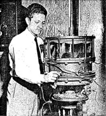
Photographs are usually taken with a large Cloud Chamber of the variety illustrated in Figure 2-6. The Cloud Chamber shown is much larger than the Gilbert type and it is cylindrical in shape. At the top of the apparatus is a glass cylinder which serves as the expansion chamber. Equipment shown below the chamber is used to expand the chamber and to control this expansion.
One usually places very strong lights around the chamber and a mechanism to flash these lights for a fraction of a second just alter the chamber is expanded. A camera then photographs the picture of the tracks. Still another type of Cloud Chamber is shown in Figure 2-7.
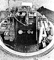
Constructed at the University of Minnesota, this rectangular chamber is a marvel of ingenuity, for it operates while suspended from huge balloons which soar up to 100,000 feet above sea level. Here, in the happy hunting ground for cosmic rays, this outfit performs a large number of operations and photographs cosmic rays which pass through the chamber. Later, the equipment parachutes to the earth below, and the film in the camera is developed to reveal the tracks of the kinds of rays which exist 20 miles up in the stratosphere.
In Figure 2-7, you will notice that there is a Geiger Counter placed above the chamber. Although you cannot see it, there is also another one below the chamber and these two form a telescope which serves as a watchdog to detect whenever a certain kind of cosmic ray goes through the chamber. When the Geiger Counter detects a ray it trips the camera and a photograph is made of the ray as it passes through the chamber.
28
It requires some skill to get your Gilbert Cloud Chamber adjusted so that you have just the right amount of liquid and the right expansion to produce good, sharp beta tracks. Alpha tracks (as you have undoubtedly discovered) are easy to see in the chamber. Turn the rubber stopper that holds the alpha source so that the alpha source is submerged in the liquid. Then mount your beta source on the glass wall of the chamber by using some Scotch tape. See 1f you can detect the beta tracks. Also try the beta source at a distance of about one foot and level with the liquid. Many of the beta particles will be absorbed in the glass wail of the chamber, but, since our beta source produces very energetic rays, you may be sure that quite a number pass into the chamber Do not be too disappointed if you do not see the beta tracks. It will be an accomplishment if you do.
You may make the particle tracks more visible by "souping up the light in the chamber. One way to do this is to get a pair of automobile headlight bulbs and put them in place of your flashlight bulbs. (This requires a 6 volt battery.) Rather than keep them on all the time you may put a switch in the lamp circuit so that you flash the lights on when the chamber is expanded.
29
So far we have used the Geiger Counter and the Cloud Chamber to track down nuclear particles. Our tracking has concentrated on the alpha particle and the gamma ray. We have found that the alpha particle, despite its high energy, is easily absorbed in a few inches of air or in a sheet of paper. The gamma ray is capable of penetrating fairly large thicknesses of material, going through most books without difficulty. In this section we shall use a new instrument called an Electroscope. With it we shall explore again the alpha particle and the gamma ray and in addition we shall investigate the beta ray in greater detail.
We know from our previous experience that the alpha particle strips off electrons from neutral atoms and converts them into ions. These ions, or electrically charged atoms, would normally find other electrons wandering around in the gas and recombine to form neutral atoms again. But if we have an Electroscope, with an ionization chamber in which there is a collecting electrode to attract the ions, they will rush toward this wire so fast that most of them will not have time to pick up any electrons and become neutral. This rush of ions through the air of the ionization chamber forms what we call an ionization current.
30
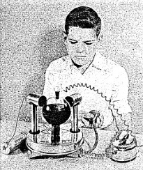
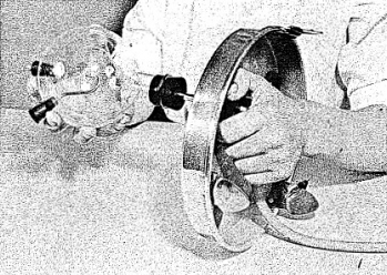
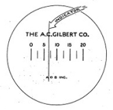
To operate your Electroscope connect the two wires to the Gilbert Dri-Electric Power Pack terminals. (See Figure 3-1.) This will light up a small bulb under the base of the chamber and it will enable you to see the screen inside the thin black tube. You will probably just see the graduated divisions on the scale. Grasp the black knob behind your viewing tube and move it until a fine image of the ion chamber needle crosses the field of view. (See Figure 3-2.) Move the knob very slowly at first until you gain experience in recognizing the image and moving it across the field. (See Figure 3-3.) Then rotate the charging knob continuously until the fiber is to the right of zero on the scale. Now rotate the knob in the opposite direction to bring the fiber to zero. A slight backing off of the knob will then stop movement of the fiber. You have now charged the Electroscope to about 200 volts.
Set the needle so that it remains at the zero mark. You may find that the needle is not always clearly visible over the length of the scale. Now bring the alpha source up under the chamber and, using a wrist watch, note how long it takes for the needle to swing across the scale. (See Figure 3-4.) The stronger the alpha source, the more rapidly will the needle swing. Thus the Electroscope can be used to measure alpha radioactivity.
31
First, let us find out how the Electroscope behaves with no radioactive materials near. Adjust the needle of the Electroscope so that it rests at zero. Note the time in your notebook. Then follow the course of the needle as it drifts along the scale. Record the needle position every few minutes. The drift rate of the needles should be very slow. It should take several hours for it to travel ail the way across the scale. It may happen, however, that your drift rate will be appreciable. Now, whenever you take a measurement with a radioactive source you should subtract the drift rate from your reading. You can, of course, set aside your instrument until a less humid day when the drift rate will be low.
In the following sections we will outline experiments far you to
perform with your alpha, beta, and gamma sources. When you carry
out these measurements it is well to keep in mind the difference
between a Geiger Counter and an Electroscope. The Geiger Counter
operates with the passage of a single ray. The Electroscope, on
the other hand, does not count each particle but operates due to
ionization produced in the Electroscope by radiation. Alpha rays
produce the strongest ionization and therefore the Electroscope is
very sensitive to these rays. Beta rays are less powerful ionizers
and the Electroscope is less sensitive to them. The Electroscope
is only slightly sensitive to the measurement of gamma rays, which
have a very low ionizing power.
32
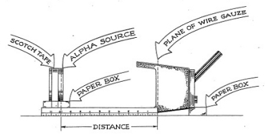
From our Cloud Chamber experiments we know that the maximum distance (range) which an alpha particle will travel in air is less than two inches. To measure the range of alpha particles in air by means of the Electroscope, set up your instruments according to Figure 3-5. Your plastic scale, with centimeter and inch division marks, should be taped to the box or support that holds the alpha source, so that the zero centimeter end just touches the screen of the Electroscope.
The support is leveled so that the alpha source is lined up with its center in line with the collecting electrode. (The collecting electrode is a small wire which you can see by looking into the underside of the Electroscope.) In this way the instrument lies on its side with the Electroscope tube facing upward. You will note that the scale of the Electroscope is now shifted in position, but this should not cause you any trouble.
Place the alpha source so that the actual surface of the alpha-emitting substance is five centimeters from the wire screen. Since the metal containing the radioactive material is two millimeters away from the surface of the plastic disc, this means that you must set the forward edge of the plastic disc 4.8 centimeters from the screen. Record the rate of swing of the indicator (quartz fiber) at this position. Make sure that you do not disturb the arrangement of the apparatus. Now, move the source one centimeter closer to the screen. Take a series of readings changing the distance one centimeter each time and record the data in your notebook in a neat row of figures.
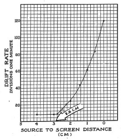
Before taking any more data prepare a rough draft of the few readings you have, plotting the points as shown in Figure 3-8, Then look over the graph, noting where you need to take more data at other scale readings in order to see more accurately the range of the alpha particles. You will notice that you must get some readings in the distance between two and three centi-
33
meters from the screen. It is a good rule to spot your observations over a wide range before taking data at small intervals. This saves time and makes for more accurate work.
Now that you have taken more data and plotted it on a graph you can see that up to about 2.8 centimeters from the screen the drift rate is fairly steady and therefore the ionization current is fairly steady. At 2.8 centimeters the ion current starts up sharply and continues ever faster until you reach the end of your scale. The reason for this is that as the source moves closer to the screen more alpha particles come within range of the Electroscope chamber. Remember that alpha particles emerge from the surface of the source going in every direction, like bits of popcorn popping out of a hot pan. Some will come out headed right for the chamber, and others will shoot out in other directions.
Off hand, it would seem that the figure 2.8 centimeters which we read from our graph is the range of the alpha particle. However, this does not agree with textbooks which state that the range is given as 3.8 centimeters. What is the reason for this one centimeter difference? If you look closely at the under side of the Electroscope you will note that the collecting electrode does not extend all the way to the wire screen. Measurements made with a general purpose Electroscope, such as the Gilbert model, need a correction factor; you must add one centimeter to the measured range of the particle to get its true range, from the source to the chamber.
34
Besides measuring the range of alpha particles in air, we can measure their absorption in thin sheets of material like paper. To prove that even a sheet of ordinary writing paper is thick enough to absorb the alpha particles, mount the alpha source on a small paper box or other support so that it is up against the screen of the Electroscope.
You can do this experiment with the instrument right side up but take care that you do not get the plastic source tilted on the little nut which holds the lamp on the screen. With the alpha source in this position take the drift rate, it should be very high. Remove the alpha source from the screen and place a single sheet of paper over it, after which replace the source under the screen as before.
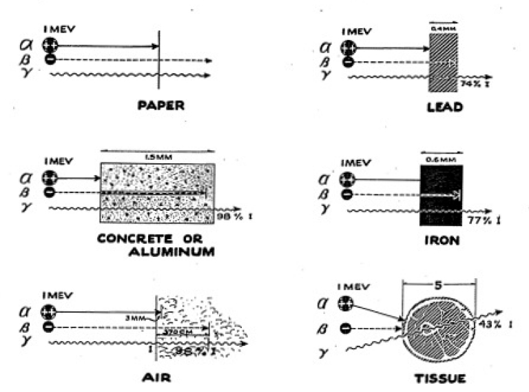
The drift rate now should be very much less, depending upon the thickness of the paper you use. You can perform a series of experiments using very thin tissue paper. For example, a single sheet of onion skin paper (as used for typewriter carbons) will allow some of the particles through. If you use two sheets of regular onion skin paper, you will find that this is enough to stop all of the alpha particles. See Figure 3-7 for absorption of alpha, beta, and gamma rays.
35
There are many other experiments which you can perform with the alpha particles emitted by your alpha source. It is hoped that you will devise experiments in your own mind and carry them out in a systematic manner. First, ask yourself what property of the alpha ray you want to investigate and then plan your experiment.
You can make a very simple gadget for giving you an alpha ray beam, although you cannot change tho direction of the alpha particles as they come from the source so that they will go in one direction.
But, follow this procedure; take a small paper tube, or a small paper box such as is used to hold gummed labels. Punch a hole in each side of the box and place this over the alpha particle source. Only those particles will emerge from the second hole which are going in the same direction as the two holes. Actually, you have created an alpha ray beam. The number of alpha particles in this beam will be quite small for you have made it by eliminating a large number of particles.
Mount the gamma source on a small box so that it is lined up with the collecting electrode of the Electroscope as we did in the case of the alpha source for range measurements. Take a series of readings starting with a source-to-screen distance of 12 inches and space your observations at 6, 4, 3, 2, 1, and 0 inches.
Remember that the real position of the radioactive material inside the plastic disc is 1/2 inch from the surface. Plot your data on a graph as before. Rather than label the upright axis of the curve as drift rate we shall now become more adult and call it the ionization current, but we can still use the same units, that is, divisions per minute.
You will note that using an Electroscope is much easier than trying to do the same experiment with a Geiger Counter. With the Electroscope, all you have to do is to take a reading, leave the instrument alone for a while, then go back and take another reading. Furthermore, the instrument is quite accurate, To demonstrate this, you can now repeat the experiment of measuring the absorption of gamma rays in a solid material.
First, let u.s try some building bricks. Set up the Electroscope on its side and place the gamma source about 9 inches away from the screen. You can check the ionization current at this position by taking a reading. Make a series of measurements after each observation adding another brick. In this way, you can construct an absorption curve simply by plotting the ionization current against the thickness of brick between the source and the Electroscope. Your exact results will depend upon your set-up as well as upon the kind of brick which you used.
36
A heavy brick will absorb more gamma rays than a light brick. Then, too, small bricks will allow some radiation to scatter, around them and reach the Electroscope chamber without passing through the brick. As a rule of thumb, you should find that 2 or 3 inches of brick will reduce the intensity of the gamma rays by about one-half.
Besides using bricks for absorbers, try using a number of other materials such as wood, concrete, aluminum, iron, and lead. You may also very profitably try using water and earth as absorbers. This requires that you use a container to hold the earth or the water. If you can obtain some lead, try making a gamma-ray howitzer. You can do this in the following way: drill a 1/2 hole in a block of lead and place the gamma ray source at the end of this hole, surrounding it with lead blocks so that a beam of gamma rays emerges through the hole. If lead is not handy, try using a 1/2" pipe and surrounding it with some heavy metal. Then you can perform absorption experiments on a beam and note the difference in absorption that results.
The howitzer produces a weak beam and you will have to be more exacting in the way you carry out your measurements for the currents will be smaller and it will take more time to get accurate data.
We have already seen that our Geiger Counter has walls which are thin enough to let through beta particles and have measured the absorption of beta rays, finding them to be more penetrating than alpha particles but less than gamma rays. We shall now look at beta rays more carefully, using the Electroscope to give us new data about these rays.
Experiments with the beta particle source must be carried out carefully. We shall see by direct experiment that the presence of any objects near the beta source is apt to scatter the electrons markedly. Thus, in doing any experiment, we must be sure that we keep the experimental conditions the same if we are to compare the results. If in one set of experiments you carry out your measurements on a concrete floor and in another you perform the work on a light wood table, you are apt to obtain different results.
As a first experiment measure the intensity of the ion current in the Electroscope for various distances of the source from the chamber and plot your results in the usual manner. Be careful to keep the Electroscope and beta source in line with each other. You can do this by securely mounting the beta source to some object, such as a box, and moving only the Electroscope. It is a good idea to perform your experiment on a thin sheet of plywood on which you can tape the beta source in an upright position. You may also mark off the distances directly (in inches and centimeters using your plastic rule) on the plywood surface.
The exact shape of the curve you obtain for intensity of beta particles versus distance will depend upon how you have the experiment set up. You can see this is true by mounting the beta source and the Electroscope well away from any surface and making a series of measurements in air with a little solid material close to the source or the chamber. Compare these results with data taken on a table top.
37
While we cannot make a real measurement of the range in air of beta particles, we can make an accurate measurement of the range in some material like glass, paper, lucite, or aluminum. All of these are common materials that should be available in the home or from a hardware store, Aluminum is the material usually used in making beta range tests. Thin sheets of aluminum are best.
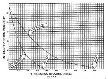
Using a little scotch tape, tape your beta source to the table or to your plywood board.. Place the Electroscope over it in an upright position and line it up so that the legs straddle the source evenly. Mark with a pencil the position of the legs so that you can easily line up the Electroscope in the same position each time. With no absorber in place, check the intensity of the ionization current, Now, slipping one sheet of material over the source, take an accurate reading, record your data arid add another sheet. Be sure to take time for your observations as more sheets are added over the source, or your readings will not be accurate.
Your results, plotted, should look like the curve presented in Figure 3-8. The results given in the illustration were made using heavy cardboard as absorbers. The dotted line in Figure 3-8 illustrates what the curve would be like for aluminum.
38
The radioactive ores will also produce a movement of the Electroscope indicator. Proceed with this experiment as you did in Section I when you used the Autunite Ore with the Geiger Counter.
We speak of the hazards of alpha and beta radiation as internal hazards, for they in general are only harmful when they get inside the body. We have seen that these particles dont penetrate as much as the gamma ray, but they might be harmful, for once they are inside the body they are, perhaps, there for a lifetime.
As we have seen, alpha particles travel only a short distance in the tissue, but they can do much damage if this tissue is important to the bodys functions. If something like radium is deposited in the bone, where it can shoot the alpha particles into the blood-forming marrow at close range, serious damage may result. This can happen if radium is inhaled or is somehow taken into the body.
We shall tell you more information about radiation hazards later
in the manual. Dont be alarmed by these things. They are just to
inform you about the dangers that may exist. These hazards have
been greatly exaggerated by the modern world. People often fear
something they know very little about. The only way to make them
forget these fears is to give them the facts of radiation hazards.
Throughout the manual you will find these facts which will show
you that you can deal with radioactivity if you can recognize it.
39