76 HYDRAULIC AND PNEUMATIC
ENGINEERING
A ship is a floating body and it displaces its own
weight of water. If, for example, a ship weighs 10,000 tons it
displaces 10,000 tons of water. If 5000 tons of cargo are
added it floats deeper in the water and displaces 15,000 tons
of water, and so on.
You will now show that a floating body displaces its
own weight of water.
EXPERIMENT No. 36
To illustrate the law of Archimedes for bodies which float.
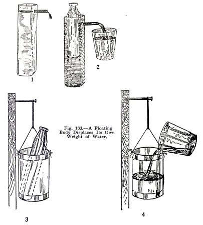
Use the empty glass bottle as the floating body. Close
the lower hole in the metal tank with a No. 1 stopper, put the
large coupling in the upper hole, fill the tank with water
until water runs out through the coupling and stops. (l)Fig.
103. Now place the bottle slowly in the water and catch the
water it displaces, (2) Fig. 103.
HYDRAULIC AND PNEUMATIC
ENGINEERING 77
Now make a spring balance with a bucket, (3), Fig.
103, as follows: Find a tin can around your home, punch two
nail holes near the top, and attach the can to the elastic
band by means of a cord, suspend the band from a nail driven
in a piece of board.
Now put the bottle in the can and mark the position of
the bottom of the elastic band. Then take the bottle out and
pour into the can the water displaced by the bottle, (4), Fig.
103. Do you find that the displaced water weighs the same as
the bottle, that is, that a floating body displaces its own
weight of water?
You have here illustrated the law of Archimedes for
floating bodies.
EXPERIMENT No. 37
To illustrate the law of Archimedes for bodies which
sink in
water.
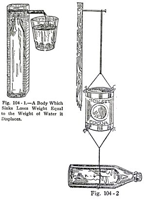
Use the bottle filled with water to represent a body
which sinks in water, fill the metal tank, Fig. 104, with
water until it overflows through the coupling and stops. Place
the bottle in the tank slowly and catch the water it
displaces.
Now attach the full bottle to the bottom of the
balance (2) and mark the position of the bottom of the rubber
band. Submerge the bottle in water (3), mark the position of
the bottom of the rubber band again, then pour the displaced
water in the can, (4). Does the balance descend to the mark
(2)? That is, is the buoyant effect on the bottle equal to the
weight of water displaced by the bottle?
78 HYDRAULIC AND PNEUMATIC
ENGINEERING
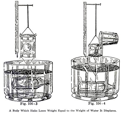
You have here illustrated the law of Archimedes for
bodies which sink in water.
RAISING
SUNKEN SHIPS
EXPERIMENT No. 38
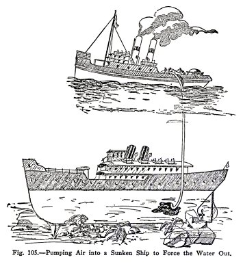
To show how sunken ships are raised by means
of air.
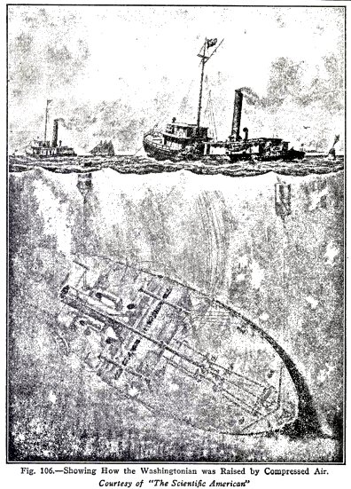
Sunken ships are raised by compressed air as
illustrated in Figs. 105 and 106. Air is pumped into the ship
until the ship and the air displace a weight of water slightly
more than the weight of the ship; the buoyant force of the
water then lifts the ship to the surface.
HYDRAULIC AND PNEUMATIC
ENGINEERING 79
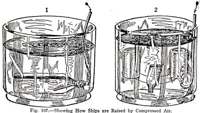
Illustrate this with the
apparatus shown in (1), Fig. 107. Fill the bottle with water
to represent the sunken ship, submerge it in a pail of water,
and blow air in through the hose. Does the ship float to the
surface?
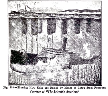
Sunken ships are also raised by means of large steel
pontoons filled with air as shown in Fig. 108.
Illustrate this as shown in (2), Fig. 107. Use the
bottle as the sunken ship and two empty tin cans of the same
size as the pontoons. Punch nail holes in the opposite sides
of the top edge of each tin can, connect them as shown, force
air into them a little at a time in equal amounts. Is the ship
raised nearly to the surface?
80 HYDRAULIC AND PNEUMATIC
ENGINEERING
HYDRAULIC AND PNEUMATIC
ENGINEERING 81
82 HYDRAULIC AND PNEUMATIC
ENGINEERING
Note: The ship would be floated into shallow
sheltered water in this way, then repaired by divers, and
floated by compressed air as described; or a coffer dam would
be built around it and the water pumped out; then the repaired
ship would float when the water was admitted to the dam.
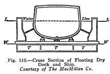
FLOATING DRY DOCKS
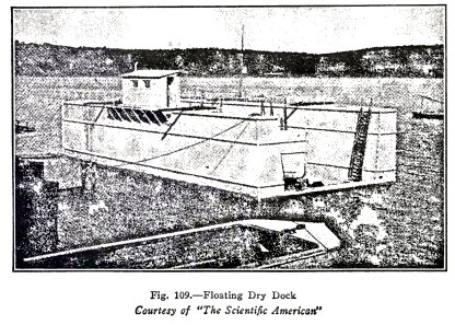
The floating dry dock, Fig.
109, is a huge steel or concrete trough shaped structure with
hollow sides and with large tanks along the bottom. It is open
at both ends and when the tanks T.T.T., Fig. 110 are filled
with water it sinks to the water line L.L. The boat then sails
into the dock and is securely braced, the water is pumped out
of the tanks T.T.T., the dock rises until the water line is at
W.W,, and lifts the ship above water.
The dry dock lifts its own weight and the weight of
the ship because it displaces a weight of water equal to
the combined weights.
HYDRAULIC AND PNEUMATIC
ENGINEERING 83
When the ship has been
repaired or when the barnacles have been scraped from its
bottom and it is ready for sea, water is again admitted to the
tanks, the dock sinks to the water line LL, and the
ship sails out.
You will now make an experiment to illustrate the
working of a floating dry dock.
EXPERIMENT No. 39
To make and operate a floating dry dock.
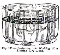
Use a flat cake pan to
represent the dry dock, and the bottle to represent the ship.
Float the dock on water in a sink or wash basin and
pour water into it until it floats with the top about 1 in.
above water. This represents the real floating dry dock, with
its tanks full, ready to receive the ship.
Float the bottle on the water in the dock. This
represents the ship, in the dock and ready to be raised.
Now siphon the water out of the dry dock and over the
edge of the sink or wash basin. This represents the water
being pumped out of the tanks of a real dry dock. Do you
observe that both the dock and the ship are raised as the
water is siphoned out? This shows how the dock and ship are
raised when the water is pumped out of the tanks of a real dry
dock.
Now siphon water from the sink into the floating dry
dock. Do you observe that the dock and the ship sink as water
enters the dock?
This represents how the real dock sinks when water is
admitted again to the ballast tanks.
84 HYDRAULIC AND
PNEUMATIC ENGINEERING
THE GLASS SUBMARINE
EXPERIMENT No. 40
To make the
glass submarine submerge and rise in water.
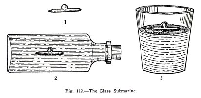
You will observe that the
glass submarine (1), Fig. 112, is hollow and that it has a
hole at the stern.
Place it in a tumbler of water. Does it float?
Place it, stern down, in the bottle full to
overflowing with water, close the bottle, turn it on its side,
and shove the stopper in hard. Does the submarine submerge?
Withdraw the stopper slightly. Does the submarine rise and
also move forward suddenly?
Repeat this with the bottle between your eyes and a
light and observe the air in the submarine. Is the air
compressed when you shove the stopper in, and does it expand
when you withdraw the stopper?
The submarine floats in the tumbler because it is
lighter than an equal volume of water. It sinks in the bottle
when you force the stopper in because sufficient water is
forced in to make it heavier than an equal volume of water. It
rises when you release the stopper because the air expands and
forces sufficient water out to make it again lighter than its
own volume of water.
Water is nearly incompressible but air is very
compressible and when you shove the stopper in you compress
the air but not the water.
HYDRAULIC AND PNEUMATIC
ENGINEERING 85
Find a larger bottle and repeat these experiments.
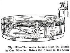
The submarine moves forward when you withdraw the
stopper because the expanding air shoots a stream of water to
the rear through the stern and this drives the submarine
forward.
Illustrate this with the apparatus Fig. 113. Does the
stream in one direction under water force the nozzle in the
other and make it writhe like a snake?
RUNNING WATER
FRICTION
As soon as water starts to run in a pipe it rubs
against the inside of the pipe and its velocity is decreased.
This rubbing is called friction and it always decreases the
flow of water.
EXPERIMENT No. 41
To illustrate the effect of friction on running water.
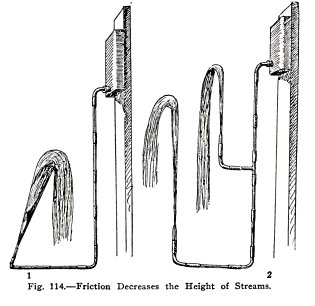
Use the apparatus, (1), Fig. 114. Raise and lower the
tank. Do you find that the stream from the nozzle never
reaches the level of the water surface in the tank?
86 HYDRAULIC AND PNEUMATIC
ENGINEERING
It does not do so because the friction in the tubes
and nozzle decrease its velocity.
Use the apparatus (2), Fig. 114. Is the lower stream longer
than the upper, but do you find that it does not reach as high
as the upper stream? It does not, because the velocity of the
water in the lower tube and nozzle is greater and therefore
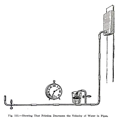
the friction is greater. Use the apparatus, Fig. 115. Allow
the water to run into the tumbler for exactly 15 seconds and
observe the amount, then close the coupling above the tee,
empty the water back into the tank, transfer the elbow to the
end coupling, and allow the water to run into the tumbler from
the end for exactly 15 seconds. Is the flow of water less from
the end? It is less because the friction in the extra pipes
decreases its velocity.
It is a matter of the greatest importance that
friction be taken into consideration in planning the piping
for any system of water supply or water power. The facts
regarding it may be stated briefly as follows :
The friction of water in pipes:
(1) Is greater in long pipes than in short pipes of
the same size.
(2) Is greater in rough pipes than in smooth pipes of
the same size.
(3) Is greater when the water is moving rapidly than
when it is moving slowly .
(4) Is greater in small pipes than in large pipes of
the same length.
HYDRAULIC AND PNEUMATIC ENGINEERING 87
NOZZLES
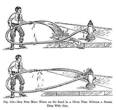
When you have been watering the road or garden you
have probably noticed that the stream is longer when you use a
nozzle than when you simply let the water flow from the end of
the hose. Have you noticed, however, that you put less water
on the road or garden in a given time with a nozzle than
without?
EXPERIMENT
No.
42
To show why the stream
is longer with a nozzle than without.
Use the apparatus (1), Fig. 117. Is the stream short
and is the pressure low? Place a nozzle in the coupling (2),
Fig. 117. Is the stream long and is the pressure high?
88 HYDRAULIC AND PNEUMATIC
ENGINEERING
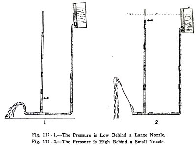
You have shown here that the stream from a nozzle is
longer than from the hose because the pressure behind it is
greater.
The pressure at any point in a pipe carrying running
water is proportional to: first, the height above the point of
the water in the tank; and second, to the fraction of the
total resistance the running water encounters beyond the
point. The pressure behind the nozzle in (2) is great because
the resistance the water encounters in the nozzle is great.
EXPERIMENT No. 43
To show that you put less water on a road in a given time with
a nozzle than without.
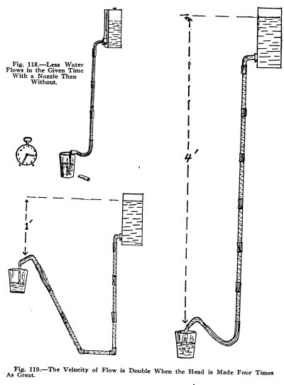
Use the apparatus, Fig. 118, allow the water to run
from the end of the hose into the tumbler for exactly 15
seconds and observe the amount, then insert the nozzle and
repeat. Is the flow less with the nozzle than without?
HYDRAULIC AND PNEUMATIC
ENGINEERING 89
VELOCITY OF FLOW
90 HYDRAULIC AND PNEUMATIC
ENGINEERING
You might think that the velocity of water from a
nozzle would be doubled when you double the height of the
water in the tank above the nozzle. You will show, however,
that you must make the height four times as great to double
the velocity.
EXPERIMENT No. 44
To show that the velocity of water is doubled when the head is
made four times as great.
Use the apparatus, Fig. 119. Allow the water to flow
into the tumbler for 15 seconds with the head exactly one
foot, observe the amount carefully, then repeat with the head
exactly four feet. Is the amount doubled?
The head is the vertical distance the water surface in
the tank is above the nozzle opening.
The velocity of water in a pipe varies as the square
root of the head. That is, if you start with a head of 1 foot,
and increase the head to 4 feet the velocity is doubled, √4 =
2; if you increase the head to 9 feet the velocity is trebbled
√9 = 3, and so on.
AIR LOCK
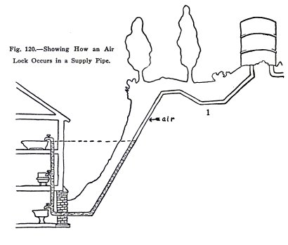
If the pipe from your water
tank to your house runs up and down hill, it may become
stopped by an air lock as shown in Fig. 120. In (1) the tank
is empty but water remains in the U part to the level of the
bathroom faucet; above this is air. In (2) the tank is again
filled and the bathroom faucet is open but the water does not
run. It does not because the air in the pipe permits the 15
HYDRAULIC AND PNEUMATIC
ENGINEERING 91
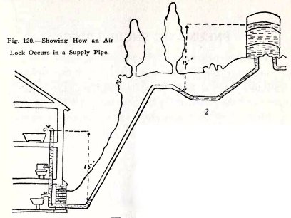
foot head at the tank to be balanced by the 15 foot
head below the bathroom faucet. This is called an air lock.
The air lock can be destroyed by opening any faucet
near the bottom of the U because these let out the water and
then the air. It can be destroyed here by opening the basement
faucet.
EXPERIMENT No. 45
To illustrate an air lock.
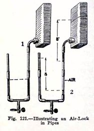
Use the apparatus, Fig. 121. In (1) the tank is empty
and the U is half full of water. In (2) the tank is filled but
the water does not run. It is air locked because the air
permits the 8 inch head in the U to balance the 8 inch head at
the tank.
Open the tee. Is the air let out? Close the tee. Does
the water flow, that is, is the air lock destroyed.?
92 HYDRAULIC AND
PNEUMATIC ENGINEERING
PNEUMATIC ENGINEERING
Pneumatic engineering is the engineering which deals
with air and other gases. You have already used two pneumatic
appliances in the section on hydraulic engineering, namely,
the siphon and the pump; these are pneumatic and also
hydraulic appliances. You have also made some experiments to
show that the atmosphere exerts pressure; you will begin your
work in pneumatic engineering by making further experiments
along this line.
ATMOSPHERIC PRESSURE
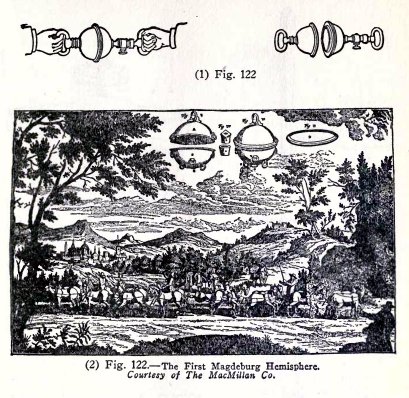
EXPERIMENT No. 46
To show that the atmosphere
exerts pressure.
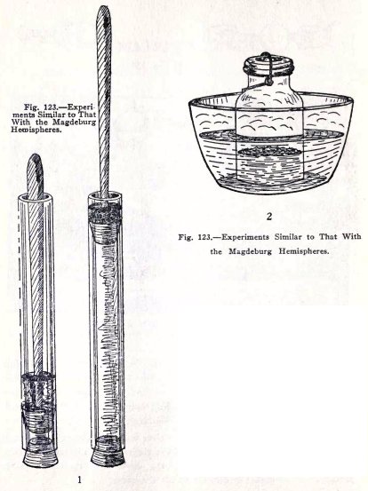
The Magdeburg hemispheres, (1) Fig. 122, are made of
metal, are hollow, and are ground smooth around the edge so
that they fit together air-tight. When the air is pumped out,
through the handle on one side, they are hard to pull apart.
The original hemispheres, (2) Fig. 122, were 14 inches in
diameter and required eight horses on each side to pull them
apart. When the air is pumped out there is nothing inside the
hemispheres to exert pressure outward and the pressure of the
atmosphere holds them together.
Show this with (1), Fig. 123. Pull the handle up and
there is very little air inside to exert pressure outward.
Pull out the end stopper. Does the atmosphere make this rather
difficult?
HYDRAULIC AND PNEUMATIC
ENGINEERING 93
Show it also with (2). Fill
the quart sealer one third full of hot water, put on the
rubber ring and the cover but do not seal, place the sealer in
a saucepan of salt water, heat until the water in sealer has
boiled for one or two minutes, seal and stand aside until
quite cold. Unseal and try to lift the cover. Is it difficult?
The steam formed in the sealer drives out the air and
when the steam condenses there is a vacuum above the water in
the sealer. There is then no upward pressure under the cover
and the atmospheric pressure on top makes it difficult to lift
the cover.
94 HYDRAULIC AND PNEUMATIC
ENGINEERING
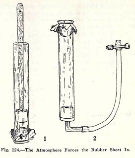
When the plunger is raised in the tube, (1), Fig. 124,
the atmospheric pressure on the outside forces the sheet of
rubber in.
Illustrate this also by means of (2), Fig. 124. Suck
air out of the tube and close the hose with a clip. Does the
atmosphere force the rubber in? Turn the rubber in all
directions. Is the pressure of the atmosphere equal in all
directions.
HYDRAULIC AND PNEUMATIC
ENGINEERING 95
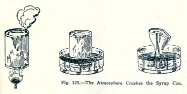
A most striking method of showing that the atmosphere
exerts pressure is shown in Fig. 125. A little water is placed
in an empty syrup can and boiled until the steam comes out for
one or two minuts.
(Sic.)
The can is then closed air tight and inverted in a dish of
cold water. In a short time the can suddenly collapses.
The reason for this is as follows: when the steam has
driven out the air there is nothing left in the can but water
and steam, and when
96 HYDRAULIC AND PNEUMATIC
ENGINEERING
the steam condenses in the closed can, there is
nothing in the space above the water, to exert pressure
outward and the can must stand the whole pressure of the
atmosphere. If it is not strong enough to do this, it
collapses.
Beg or buy a gallon syrup can and try this experiment,
it will certainly surprise you. Be sure the opening is covered
with water when you invert the can in cold water because the
water will help to make the opening air-tight.
You cannot make this experiment with a glass bottle
because the glass is strong enough to support the atmosphere.
HOW ATMOSPHERIC PRESSURE WAS FIRST MEASURED
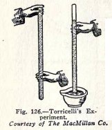
The pressure of the atmosphere was first measured by
an Italian named Torricelli in 1643, with apparatus similar to
that shown in Fig. 126. His experiment was essentially as
follows: A glass tube, 3 feet long and closed at one end, was
completely filled with mercury (quicksilver) to expel the air;
the open end, closed with the finger, was then inverted over a
dish of mercury, and the finger was removed under mercury.
He found that some of the mercury came out of the tube
but that a column remained to a height of about 30 inches
above the surface of the mercury in the dish.
Since no air enters the tube, the space above the
mercury in the tube has nothing in it, that is, it is a
vacuum. There is, therefore, no pressure downward on the
surface of the mercury in the tube, and the pressure of the
atmosphere downward on the surface of the mercury in the dish
supports the column of mercury in the tube.
HYDRAULIC AND PNEUMATIC
ENGINEERING 97
HOW THE PRESSURE OF THE ATMOSPHERE IS MEASURED
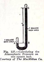
If this experiment is repeated with the tube shown in
Fig. 127, the top of the mercury in the long closed tube is 30
inches above the top of the mercury in the short open tube.
Since, as you will show shortly, this height is independent of
the area of cross section of the tube, we can consider this to
be just 1 square inch.
The pressure of the atmosphere on 1 square inch at A,
then, supports a column of mercury BC which is 1 square inch
in area and 30 inches high, that is, it
supports 30 cubic inches of mercury.
Now 1 cubic inch of mercury weighs .49 lbs. (nearly
1/2 lb.) and 30 cubic inches of mercury weigh .49 x 30 = 14.7
lbs. The pressure of the atmosphere is therefore 14.7 lbs. per
square inch, (nearly 15 lbs. per square inch).
It is a very astonishing fact that the atmosphere
exerts 14.7 lbs. pressure on each square inch of every thing
at the surface of the earth. It is at first almost
unbelievable, but you have already made experiments which
illustrate this pressure and you will make others as you
proceed.
EXPERIMENT No. 47
To measure the pressure of the atmosphere.
If you have a spring balance you can measure the
pressure of the atmosphere directly with the apparatus, Fig.
128, as follows.
The diameter of the plunger is a little over 5/8
inches and therefore its area is 3/10 square inch. If then the
pressure of the atmosphere is 15 lbs. on 1 square inch it is
15 x 3/10 = 4 1/2 lbs. on 3/10 square inch.
Soap the plunger well to make it slippery, shove it
about 3/4 way into the tube, fill the remaining 1/4 of the
tube with water, and insert a solid rubber stopper in this
end, (1). Now turn the tube so that the plunger handle points
vertically upward, and pour a little water in above the
plunger to make it air-tight, (2).
98
HYDRAULIC AND PNEUMATIC ENGINEERING
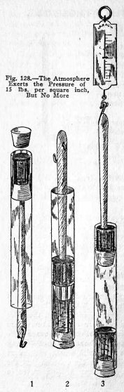
Now to measure the pressure of the atmosphere, attach
the plunger handle to a spring balance, hold the tube firmly
against the table, and ask your partner to pull upward on the
spring balance while you observe the pull recorded on the
balance, (3).
Ask him to lift the balance slowly until the plunger
is about two inches above the water, then ask him to allow the
balance to go back slowly until the plunger is only about 1
inch above the water. While he is doing this you must read the
average pull on the balance.
Do you find this average pull to be 72 ozs. or 4 1/2
lbs?
Note: While
your partner is raising the plunger, the friction of the
plunger against the sides of the tube is working against the
balance and the pull will be over 4 l / 2 lbs; but while he is
lowering the plunger, the friction will be working with the
balance and the pull will be less than 4 1/2 lbs. The average
will be about 4 1/2 lbs.
You have shown here that the pressure of the
atmosphere is 4 1/2 lbs. on 3/10 sq. in. or 4 1/2 x 10/3
= 15 lbs. on 1 square inch.
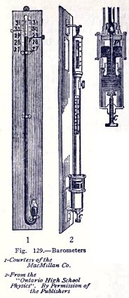
THE BAROMETER
The barometer, Fig. 129, is the chief instrument used
by the Weather Bureau in forecasting the weather. It Is an
apparatus similar to that used by Torricelli in his
experiment. The pressure of the atmosphere on the mercury in
the open tube or cup supports a column of mercury about
HYDRAULIC AND PNEUMATIC
ENGINEERING 99
30 in. high in the long closed tube. The pressure of
the atmosphere varies from hour to hour and the height of the
mercury column varies with it. Weather forecasts are based on
this variation.
It has been found that when the mercury falls much below 30
in., because the atmospheric pressure is low, bad weather may
be expected; and when the mercury rises much above 30 inches,
because the atmospheric pressure is high, good weather may be
expected. The extreme variations are from about 29 in. to 31
in.
The barometer (2) is the type used on ships, and when
a sailor says "the glass is falling" he means that the mercury
in the glass tube is sinking below 30 in. and that bad weather
is to be expected; when he says "the glass is rising," he
means that the mercury is rising above 30 in. and that fine
weather is to be expected.
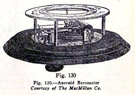
Another type of barometer is shown in Fig. 130. It is
called an aneroid barometer because it contains no liquid. It
has a flat, round, air tight metal box from which the air is
exhausted. The atmospheric pressure would force together the
top and bottom of this box if they were not kept apart by the
strong spring shown
100 HYDRAULIC AND PNEUMATIC
ENGINEERING
above the box. If the atmospheric pressure increases,
the spring is forced down; if the pressure decreases, the
spring rises. The movements are very small, but they are
magnified by levers and are communicated to the pointer by
means of a rack and pinion.
HOW AIRMEN KNOW THEIR ALTITUDE
THE ALTITUDE GAUGE
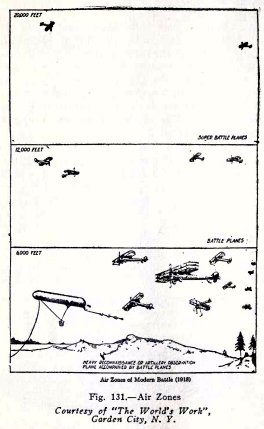
The air zones of a modern
battle are illustrated in Fig. 131 and the altitude gauge by
means of which the airmen know their height is shown in Fig.
132. This altitude gauge is a recording aneroid barometer
called a barograph. It records the height of the airplane in
feet and is suspended free of the airplane by four elastic
straps which protect it, to some extent, from the vibration of
the machine.
The construction of the barograph is as follows. It
has five or six flat metal boxes, exhausted of air, similar to
the box in the ordinary aneroid. These boxes are expanded by a
strong spring, as the height increases, and this movement is
communicated to the long pointer. On the end of the
pointer there is a pen, with a supply of ink, which bears
against a sheet of paper on a drum revolved by clockwork. The
pen makes a continuous record on the paper of the height in
feet.
 The
Science Notebook
The
Science Notebook