126 HYDRAULIC AND PNEUMATIC
ENGINEERING
firmly, turn the bottle upside down and shake. Does
the gas drive the water out with considerable force?
Repeat the experiment but this time make a cigarette
shaped tissue paper package of the baking soda and attach the
open end to the underside of the stopper by means of a pin.
The extinguisher then will work when you turn it upside down.
Repeat but use the white and blue packages of a
Seidlitz powder instead of the vinegar and soda. Dissolve the
contents of the blue package in the water and dump in the
contents of the white. They produce carbon dioxide gas.
EXPERIMENT No. 63
To show how
carbon dioxide gas puts out a fire.
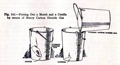
You can show that the carbon dioxide gas (CO) is heavy
and that it will put out a fire as follows : Pour six
tablespoonsful of vinegar into an empty ten-quart pail, Fig.
162, and add one level tablespoonful of baking soda. Stir with
a spoon until the fizzing stops. You now have the bottom of
the pail full of carbon dioxide gas. You cannot see it but it
is there. Now light a match and lower it slowly into the pail.
Does it go out when it gets a certain distance into
the pail? It goes out because it is surrounded by carbon
dioxide gas which does not support combustion.
HYDRAULIC AND PNEUMATIC
ENGINEERING 127
Light a candle and lower it into the pail in the same
way. Does it go out? It goes out for the reason stated above.
You know that (CO2) gas is heavier than air
because it remains in the bottom of the pail. If it were
lighter, the air would sink to the bottom of the pail and lift
it out.
You can show that the (CO2) gas is heavy
and that it will pour just like water, as follows: Put a
lighted match or a very short lighted
candle at the bottom of an empty pail, then lift the
pail containing the CO2 gas and pour it into the
empty pail just as you would pour water.
Does the gas put out the match or candle? This shows
that the gas pours and therefore that it is heavier than air.
It also shows again that the CO2 gas puts out a
fire.
THE AIR PUMP
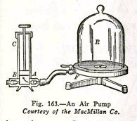
The air pump shown here has a solid plunger and two
valves A and B; valve A opens inward and valve B outward. The
vessel R, out of which the air is being pumped, has an open
bottom with a ground edge which fits air-tight on the smooth
greased surface of the stand. The air is pumped out through a
hole in the center of the stand and through the pipe F.
When the plunger is pulled up, valve B closes and part
of the air expands from the vessel R through A into the pump
cylinder C. When the plunger is forced down, valve A closes
and the air in C is forced out through the valve B.
When the plunger is again raised part of the air
remaining in R expands into C and when the plunger is forced
down this air is forced out through B, and so on.
If you wish to pump air into R you attach it to B
instead of to A and operate the plunger. Each stroke of the
plunger fills the cylinder C with air and each down stroke
forces this air into R.
128 HYDRAULIC AND
PNEUMATIC ENGINEERING
EXPERIMENT No. 64
To make and operate an air pump.
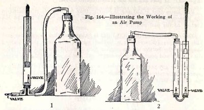
Arrange the apparatus as in (1) Fig. 164 and operate
the plunger. Do you pump air out of the bottle?
Arrange the apparatus as in (2) Fig. 164 and operate
the plunger. Do you pump air into the bottle?
THE BICYCLE PUMP AND TIRE
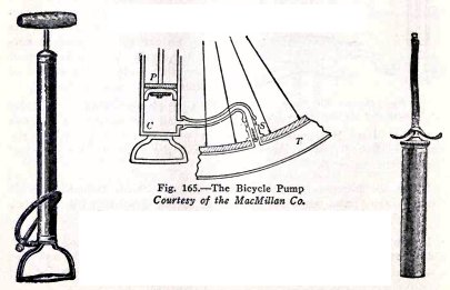
The bicycle pump is a very simple air pump. It
consists of a cylinder C and a plunger P; one valve is the cup
shaped piece of leather on the bottom of the plunger, and the
other is the valve S which remains on the bicycle tire, T,
HYDRAULIC AND PNEUMATIC
ENGINEERING 129
When the plunger is moved up there is a vacuum left in
the space C beneath, and the pressure of the atmosphere forces
air into this space around the sides of the cup valve which
bends in. When the plunger is forced down, the air in C is
forced into the tire through the valve S, because the cup
leather is forced outward by the air pressure and becomes
air-tight. This is repeated at each stroke.
The hand pump, at the right has a hollow plunger stem
through which the air passes to the tire. A cup leather on the
plunger is one valve and the valve on the tire, the other.
EXPERIMENT No. 65
To make and operate two bicycle pumps.
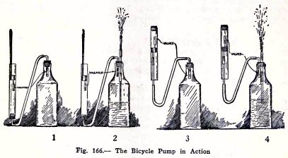
Arrange the apparatus as in (1) and operate the
plunger. The bottle with its valve represents the bicycle tire
with its valve. Do you pump air into the tire?
Arrange the bottle as in (2) and pump air into it.
Does the compressed air force the water out?
The above represents the action of a large bicycle
pump. Make the experiments (3) and (4). The pump here
represents a hand bicycle pump.
130 HYDRAULIC AND PNEUMATIC ENGINEERING
THE AIR COMPRESSOR
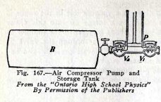
The commercial air compressor is simply a large air
pump as shown in Fig. 167. It has a solid plunger P and two
valves. When the plunger is raised, the pressure of the
atmosphere lifts valve V1 and forces air into the
pump barrel; when the plunger is driven down, valve V1
closes but valve V2 opens and the air is forced
into the storage tank R. This operation is repeated at each
stroke. The pump is driven by a steam engine, gasoline engine,
electric motor, or water wheel.
THE SAND BLAST
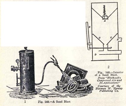
The sand blast, one form of which is illustrated in
(1) Fig. 168, is used to clean metal castings, etch glass, cut
the letters in marble, clean the walls of buildings, and so
on.
The sand is driven by compressed air with great force
against the object to be cleaned. Each particle of sand
pulverizes the material which it strikes and since millions of
grains strike the material each minute, the surface is worn
away very rapidly.
HYDRAULIC AND PNEUMATIC
ENGINEERING 131
The inside of the machine is represented in (2) Fig.
168. The sand is dumped into the V shaped top and is admitted
to the chamber CC below through the valve A. The compressed
air enters at B and passes out to the hose and nozzle through
the tube D. The sand is dropped into the moving air through
the valve F and is carried through the hose and nozzle to the
object.
EXPERIMENT No. 66
To make and operate a sand blast.
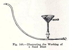
Arrange the apparatus as shown in Fig. 169. The sand
is held in the funnel and drops down into the moving air when
the clip is opened.
Fill the funnel with dry, coarse sand and ask your
partner to hold his hand over the funnel and open the clip,
while you blow air into the hose and hold your
hand opposite the tee opening to feel the effect.
Your partner's hand must be held over the funnel,
otherwise part of the air will blow up through the sand.
Repeat this with the bottle used as a compressed air
tank. Pump air into the tank by means of a bicycle pump, and
close the hose with a clip. Connect the hose with the tee, ask
your partner to hold his hand over the funnel and open the
funnel clip, then hold your hand in front of the tee opening,
and open the clip on the hose.
Do you find that the sand strikes your hand with
considerable force?
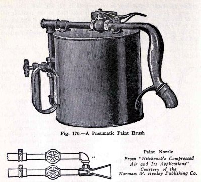
PNEUMATIC
PAINT BRUSH
The working of the pneumatic paint brush is as
follows: The compressed air enters through the hose and handle
and issues from a small nozzle. The current of air thus
produced carries out with it the air around the nozzle and
creates a partial vacuum. The atmospheric pressure on the
paint in the tank then forces paint into the vacuum around the
nozzle, and this paint is carried out through the large nozzle
by the air current. The air pressure is from 50 to 80 tbs. per
sq. in. and the stream of paint can be regulated from a fine
mist to a solid stream.
132 HYDRAULIC AND PNEUMATIC
ENGINEERING
This form of paint brush is used in all kinds of
painting and permits very rapid work. It is used in painting
buildings, bridges, machinery, railway cars, furniture and
even pictures, also in calsomining and white-washing walls,
houses and fences, and in spraying disinfectants in hospitals,
camps, trenches, hen houses, etc. The common atomizer is made
on the same principle.
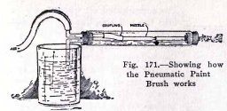
EXPERIMENT No. 67
To make and operate a pneumatic paint brush.
Arrange the apparatus as in Fig. 171 and blow hard
into the rubber tube.
Do you observe that water rises from the tumbler into
the wide tube, and issues from the narrow tube in the form of
a light spray?
HYDRAULIC AND PNEUMATIC
ENGINEERING 133
This is very interesting, because it shows that
although you blow air into the wide tube you create a partial
vacuum in the tube. The reason for this is as follows : The
compressed air from the nozzle enters the narrow tube with
great velocity and in doing so carries air from the wide tube
along with it. This creates a partial vacuum in the wide tube
and the pressure of the atmosphere lifts water from the
tumbler into the wide tube. The water is then carried into the
narrow tube by the stream of compressed air and issues from
the end.
THE DIVING BELL
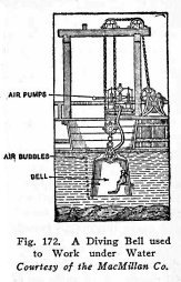
The diving bell, Fig. 172, is simply a large iron bell
open at the bottom. It is used to enable men to work on the
bottom of a river, lake, or ocean, for example, to lay the
foundations of bridges, wharves, lighthouses, etc.
The bell is made large enough to hold a number of men,
heavy enough to sink readily in the water, and strong enough
to stand the great pressure of the water on the outside. It is
usually carried in a ship in a special compartment called
a well: this is simply a hole in the bottom of the ship, lined
up on all sides to prevent water from entering the ship. The
bell is raised and lowered by means of a winch and pulleys,
and is supplied with compressed air through a strong rubber
tube attached to an air pump on the ship.
When it is desired to use the diving bell, the sailors
first anchor the ship fore and aft over the spot where the
work is to be done, then the workmen get into
the bell through the bottom, the air pump is started, and the
bell is lowered by means of the winch and pulleys.
134 HYDRAULIC AND PNEUMATIC
ENGINEERING
The compressed air which is forced into the bell
supplies the men with fresh air and also prevents the water
from entering the bottom of the bell; the excess air escapes
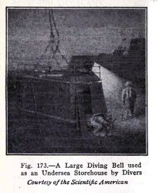
in bubbles under the edge of the bell. A form of diving bell
used by divers is illustrated in Fig. 173. It is lowered by a
heavy cable from a ship at the surface, from which it is
supplied with compressed air, electricity, and telephone
connection. The diver carries his air in a tank on his back
and is therefore not encumbered by a heavy air hose; the light
cable which he drags is his telephone connection. The bell
serves as a store house for tools and as a place to which the
diver can retreat to repair his suit if necessary. He enters
and leaves the bell through an opening near the bottom as
shown.
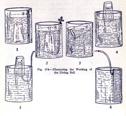
EXPERIMENT No. 68
To make and operate a diving bell.
Place a piece of a match stick on the surface of the
water in a wash bowl. Invert an empty tumbler over the match
and force the tumbler to the bottom of the bowl without
letting air escape. Do you notice that the water enters the
tumbler only to a very sligh extent and that you can make the
match rest on the bottom of the bowl.
The tumbler represents the diving bell and the match
stick represents the man, who could now go to work on the
bottom of the river or lake. Of course, the man in a regular
diving bell would not get into the water first but would stand
or sit on a shelf inside the bell. Raise the tumbler gradually
and notice that the water lifts the match up again.
In this experiment the lower edge of the diving bell,
the tumbler, is only six or eight inches under the surface of
the water, therefore the
HYDRAULIC AND PNEUMATIC
ENGINEERING 135
pressure of the water upward on the air in the bell is
small, and the air is only slightly compressed. When the
regular diving bell is sunk in water, however, the pressure of
the water upward on the air in the bell increases as the
bell sinks deeper and deeper and the water would rise in
the bell, were it not that the compressed air is pumped in at
sufficient pressure to overcome this water pressure and to
keep the water out.
Repeat the experiment with the hose as in (2). Open the hose.
Is the air forced out? Blow air into the hose. Is the water
forced out?
Lift a boat above the water level as in (3), (4) and
(5). Make the experiment with the metal tank used as the
diving bell (6).
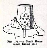
EXPERIMENT No. 69
To make a home-made diving bell.
You can have fun in your swimming pool by using either
a 12 qt. pail, a wash boiler, or a wash tub, as a diving bell.
Do this as follows :
Place the inverted pail over your head and let
yourself sink. You will find that you can breath under the
pail for a short time but that the
136 HYDRAULIC AND PNEUMATIC
ENGINEERING
air soon needs renewing. You will find also that you
cannot sink very far, because the buoyancy of the inverted
pail is greater than the weight of your body in water.
Repeat the experiment with a wash boiler or wash tub.
You will find again that you can breath under the boiler or
tub. You will find also that you cannot sink the boiler or tub
because their buoyancy, when inverted and filled with air, is
much greater than the weight of your body in water.
Make this experiment. Go to a part of the swimming
pool where you can sit on the bottom with your head above
water, then let two of your friends place the tub, upside
down and full of air, over your head and force it down gently
until the bottom of the tub is slightly under the surface.
Your head is now below the level of the water outside, but you
will find that you have plenty of air in the tub because the
water level in the tub is only slightly above the level of the
edge of the tub.
Make experiments of your own.
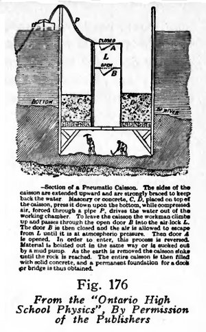
PNEUMATIC CAISSONS
A caisson similar to that shown here is used to remove
the earth down to the rock for the foundations of bridge
piers. It is filled with compressed air which drives the water
out at the bottom and leaves the earth dry for the workmen.
The caisson is closed in on all sides to keep out the
water. It is open at the bottom but is closed above by well
braced timbers weighted down by concrete CD. The bottom is let
down into the mud, the compressed air is turned on to force
the water out of the working chamber, and the workmen then
enter the working chamber to excavate the mud. The weight of
the concrete CD. gradually sinks the caisson, as the mud is
excavated, until the solid rock is reached.
The men enter the caisson through the air lock L, as
follows: The lower door B is closed, compressed air is let out
of L, the door A is
HYDRAULIC AND PNEUMATIC
ENGINEERING 137
opened, the workmen enter, the door A is closed and
compressed air is admitted slowly to L until its pressure is
equal to that below; the door B is then opened and the men
climb down a ladder into the caisson. The men leave, and mud
is lifted out through the air-lock by the reverse proceedure.
When the caisson is down to the rock, the working
chamber and the space above are filled with concrete to serve
as the foundation of the bridge. Sometimes the outer casing of
the caisson is removed, but more often it is left where it is.
EXPERIMENT No. 70
To make and operate a pneumatic caisson and to show
how a man enters it through the air-lock.
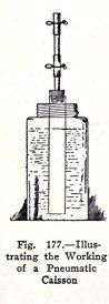
Arrange the apparatus as shown in Fig. 177. The wide
tube represents the caisson and the narrow tube at the top,
the air-lock; the clips represent the upper and lower doors of
the air-lock.
Put the caisson, with both clips open, in the sealer
full of water.
Do you find that the water level inside the caisson is
the same as that outside?
Now blow air in through the air lock and close one or
both clips.
Do you find that the water level inside the caisson is
now at the bottom?
This illustrates the manner in which compressed air
forces the water out at the bottom of a real caisson.
Now to show how a man enters the caisson
without letting out the compressed air, proceed as
follows:
Use a pin to represent the man, be sure that both
Caisson doors are closed, then open the upper door and drop
the pin into the air-lock head downwards, not that the
138 HYDRAULIC AND PNEUMATIC
ENGINEERING
man enters head downwards, but the head of the pin
will not stick into the rubber as the point might.
Now open the lower door.
Does the pin drop to the bottom and has the whole
operation been completed without letting air out of the
caisson or water into it.
This represents the way a man would enter the caisson.
It is called "locking in". The man of course would not drop
from the air lock to the bottom of the caisson; he would climb
down a ladder. Tools and materials are admitted to the caisson
in the same way, and removed by reverse operation.
EXPERIMENT No. 71
To show how a torpedo is shot out of a submarine or
battle ship.
A torpedo is fired out of a submarine or battle ship
by means of compressed air and is kept in motion after it is
fired by means of a compressed air motor.
Show how the torpedo is fired, by means of the
apparatus Fig. 179. The bottle here represents the compressed
air tanks on the battleship, the wide tube represents the
torpedo tube and the plunger, the torpedo.
HYDRAULIC AND PNEUMATIC
ENGINEERING 139
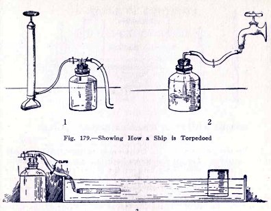
Close the bottle by means of cord and rubber bands and
compress air in it by means of a bicycle pump (1) if you have
one ; if not, attach the rubber tube to a water faucet by
means of an elbow and stopper (2) and fill the bottle half
full of water in order to compress the air to half its first
volume and thereby give it a pressure of 15 lbs. per sq. in.
Connect the bottle with the torpedo tube, point the tube at
the ship (3) and open the clip. Do you torpedo the ship in a
very realistic manner
EXPERIMENT No. 72
To show how the men in a submarine could be supplied
with air taken from sea water.
Arrange the apparatus as in (1) Fig. 180. The space
between the stoppers is completely filled with water and is
free from air; the plunger is covered with water to make it
air-tight.
140 HYDRAULIC AND PNEUMATIC
ENGINEERING
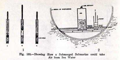
Now lift the plunger as in (2). Do you observe that
air bubbles come out of the water? Let the plunger go back
(3). Do you observe that there is a small bubble of air
between the rubber stoppers? This is extremely interesting and
is explained as follows: All water on the earth which is
exposed to the air has air dissolved in it, (the fish in water
live on this air). When you lift the plunger you produce a
vacuum above the water and thereby reduce the pressure on the
water to zero. The air in the water then expands into bubbles
and escapes from the water.
Submarines could be supplied with pure air when under
water as follows: They would need a pump similar to your
apparatus above but arranged as follows: During the upstroke
of the plunger the inlet valve would open for say only 1/4 of
the stroke and then close for the remaining 3/4 of the stroke.
The plunger would thus draw in water during 1/4 stroke, and
would produce a vacuum above the water for the remaining 3/4
stroke, the air in the water would then expand and escape from
the water.
On the down stroke of the plunger the air and water
would be forced out of the pump but on their way out of the
submarine they would pass through a tank, the air would escape
into the tank but the water would pass on out. The air
accumulated in the tank could then be used in the submarine.
FINIS
HYDRAULIC AND PNEUMATIC
ENGINEERING 141
TABLE OF
CONTENTS
HYDRAULIC ENGINEERING
WATER SUPPLY.
Experiment
1. To make and operate a city water supply system in
which the water comes from a standpipe, reservoir, or lake.
2. To make and operate a private water supply system in
which the water is stored in a tank on a tower.
3. To make and operate a private water supply system in
which the water is stored in an attic tank.
4. To show how water is brought from an elevated well or
spring.
Game
1. A Naval Battle.
PNEUMATIC TANK SYSTEM OF WATER SUPPLY.
Experiment
5. To make and operate a pneumatic tank.
Game
2. Rapid Fire Water Gun.
Experiment
6. To make and operate a pneumatic tank system of water
supply.
WATER AND AIR.
7. To show that water is incompressible and that air is
compressible.
8. To show that compressed air exerts pressure.
Game
3. Trench Gun.
4. Height and Distance Contest
5. Pop Gun.
THE SIPHON.
Experiment
9. To make and operate a siphon.
HOW THE SIPHON IS USED
IN WATER SUPPLY SYSTEMS.
10. To show how the siphon is used in water supply
systems.
HOW TO START A LARGE
SIPHON.
11. To illustrate different methods of starting a large
siphon.
OTHER USES OP THE
SIPHON.
12. To illustrate other uses of the siphon.
VELOCITY OF FLOW.
13. To show that the velocity of the water in a siphon
is greater the greater the vertical distance between the water
levels about the two arms.
OTHER SIPHONS.
14. To make and operate a double siphon and a
three-legged siphon.
HOW TO START A SMALL
SIPHON.
15. To illustrate two ways of starting a small siphon.
AN INCLOSED FOUNTAIN.
16. To make and operate an inclosed fountain.
142
HYDRAULIC AND PNEUMATIC ENGINEERING
ATMOSPHERIC PRESSURE.
AIR HAS WEIGHT.
AIR EXERTS PRESSURE.
Experiment
17. To show that the atmosphere exerts pressure.
18. To show that the atmosphere will support a column of
water.
19. To prove that it is the pressure of the atmosphere
which lifts the water.
20. To show in other ways that the atmosphere exerts
pressure downward and upward.
21. To illustrate two simple uses of atmospheric
pressure
THE "WHY" OF THE SIPHON,
PUMPS.
22. To illustrate the action of a syringe.
Game
6. Water Gun Shooting.
7. Big Gun Battle.
8. Machine Gun Battle.
9. The Diablo Whistle.
Experiment
THE LIFT PUMP.
23. To make and operate a lift pump.
THE FORCE PUMP.
24. To make and operate a force pump.
25. To show how water is pumped into an elevated tank.
Game
10. Force Pump Contest.
HYDRAULIC APPLIANCES.
PASCAL'S LAW.
Experiment
26. To show that pressure exerted on water is
transmitted equally in all directions.
27. To make and operate a hydrostatic bellows.
THE HYDRAULIC PRESS.
28. To make and operate a hydraulic press.
THE HYDRAULIC ELEVATOR.
29. To make and operate a hydraulic elevator.
HYDRAULIC LIFT - LOCKS.
CANAL LOCKS. LIFT
LOCKS.
30. To make and operate a hydraulic lift-lock.
THE PRESSURE EXERTED BY
WATER.
31. To show that the pressure at a nozzle is independent
of the size and shape of the tank and pipe.
THE HYDROSTATIC
PARADOX.
32. To illustrate the hydrostatic paradox.
EXPLANATION OF
HYDROSTATIC PARADOX.
HOW TO CALCULATE THE
PRESSURE EXERTED BY WATER.
HYDRAULIC AND PNEUMATIC
ENGINEERING 143
PRESSURE
UNDER WATER.
THE DEPTH BOMB, TORPEDO
AND SUBMARINE.
Experiment
33. To show that the pressure under water increases with
the depth and that it is equal in all directions at any depth.
34. To show that water exerts pressure upward on anything under
its surface and that this upward pressure is equal to the
downward pressure at any depth.
HOW TO CALCULATE THE
PRESSURE ON DEPTH BOMB, TORPEDO, AND SUBMARINE.
BUOYANCY
WHY DOES A STEEL SHIP
FLOAT?
Experiment
35. To illustrate the buoyant effect ot water.
THE LAW OF ARCHIMEDES.
36. To illustrate the law of Archimedes.
37. To illustrate the law of Archimedes for bodies which
sink in -water.
RAISING SUNKEN SHIPS.
38. To show how sunken ships are raised by means of air.
FLOATING DRY DOCK.
39. To make and operate a floating dry-dock.
THE SMALL SUBMARINE.
40. To make the small submarine submerge and rise in
water.
RUNNING WATER.
FRICTION.
41. To illustrate the effect of friction on running
water.
NOZZLES.
42. To show why the stream is longer with a nozzle than
without.
Experiment
43. To show that you put less water on a road in a given
time with a nozzle than without.
VELOCITY OF FLOW.
44. To show that the velocity of water is doubled when
the head is made four times as great.
AIR LOCK.
45. To illustrate an air lock.
PNEUMATIC
ENGINEERING
ATMOSPHERIC PRESSURE.
Experiment
46. To show that the atmosphere exerts pressure.
HOW ATMOSPHERIC
PRESSURE WAS FIRST MEASURED.
47. To measure the pressure of the atmosphere.
THE BAROMETER.
HOW AIRMEN KNOW THEIR
ALTITUDE.
THE ALTITUDE GAUGE.
144 HYDRAULIC AND PNEUMATIC
ENGINEERING
THE WATER BAROMETER.
Experiment
48. To show that the vertical height to which the
atmosphere will lift water is independent of the length and
slant of the tube.
49. To show that the height to which the atmosphere will
lift water is independent of the size and shape of the tube and
of the water surface outside the tube.
50. To show that the atmosphere lifts heavy salt water
to a less height, and light gasoline to a greater height, than
it lifts fresh water.
51. To show that the atmosphere will lift weights.
52. To show that the atmosphere will lift 15 lbs. per
square inch but no more.
AIR-LIFT PUMPS.
53. To make and operate two air-lift pumps.
LAWS WHICH APPLY TO
GASES.
PASCAL'S LAW.
54. To illustrate Pascal's law as it applies to gases.
BALLOONS AND THE
BUOYANT FORCE OF AIR.
THE LAW OF ARCHIMEDES
APPLIED TO AIR.
HOW THE TOTAL LIFT OF A
BALLOON IS CALCULATED.
Experiment
55. To illustrate the buoyant force of air.
56. To illustrate the buoyant force of air by means of a
balloon filled with hydrogen.
57. To shoot down a balloon.
58. To illustrate the buoyant force of a gas heavier
,than air by means of a soap bubble filled with air.
COMPRESSED AND EXPANDED GASES.
BOYLE'S LAW.
59. To illustrate Boyle's law.
THE AIR BRAKE.
60. To make and operate an air brake and to illustrate
the working of the triple valve, cylinder, air tank, and train
pipe.
THE FLAME THROWER.
61. To illustrate the action of the flame thrower.
THE FIRE EXTINGUISHER.
62. To make and operate a fire extinguisher.
63. To show how carbon dioxide gas puts out a fire.
THE AIR PUMP.
64. To make and operate an air pump.
THE BICYCLE PUMP AND
TIRE.
65. To make and operate a bicycle pump.
THE AIR COMPRESSOR.
THE SAND BLAST.
66. To make and operate a sand blast.
PNEUMATIC PAINT BRUSH.
67. To make and operate a pneumatic paint brush.
THE DIVING BELL.
Experiment
68. To make and operate a diving bell.
69. To make a home-made diving bell.
PNEUMATIC CAISSONS.
70. To make and operate a pneumatic caisson and to show
how men enter it through the air-lock.
71. To show how a torpedo is shot out of a submarine or
battle ship.
72. To show how the men in a submarine could be supplied
with air taken from sea water.
MEMORANDUM PAGES
 The
Science Notebook
The
Science Notebook