51 GILBERT SIGNAL
ENGINEERING
heliograph signals can be read
up to forty or fifty miles, and even greater distances are on
record. However, the normal range is around twenty-five miles,
and to obtain longer distances it is usually necessary to
operate from a large hill or mountain peak.
The principal disadvantage to heliographing lies in its
dependence upon the sunlight. The advantages are portability
of equipment ; great range signals can be exchanged ; the
rapidity of sending; and most important of all is the fact
that your signals cannot be observed by others unless they
happen to be on the line of flash between the sending and
receiving station.
Heliograph instruments vary in design according to the
organization using them, but all are alike in principle. The
chief parts of the equipment for a station consist of one sun
mirror, one station mirror, a shutter arrangement of some sort
for intercepting the flashes and a device for directing or
sighting flashes on receiving station.
The Heliograph and Theory. Every boy has at some time taken a
small pocket mirror or bright piece of metal from which he has
reflected the sun's rays on a shadowed wall. The result on the
wall is a bright sun spot or flash which can be moved at will
by slightly shifting the mirror. As this flash is the
important factor in heliographing, it must be produced and
directed at the receiving station with a great deal of skill.
The mirrors used in heliographs are usually not over 4 or 5
inches square. Two mirrors are made necessary by the position
of the sun at time one is sending. When the sun is at right
angles to the line joining the two stations, only one mirror
is used the sun mirror. With sun at rear of operator, the two
mirrors are required.
With one mirror the flash is reflected directly from it to
receiving station and with two mirrors the flash is reflected
from
52 GILBERT BOY ENGINEERING
the sun mirror to the station
mirror and thence to the receiving station. (See Figure 11, A
and B.)
How Heliograph Operates With
One Mirror. The sun mirror has in center a small peep
hole or unsilvered spot about one-quarter inch in diameter.
The sighting device is about 6 or 8 inches to front of the
mirror. An upright rod is generally employed which can be
moved up and down; the rod sets parallel with edge of mirror
and has a round disc on an arm which when turned at right
angles to rod falls in line with center of mirror.
To direct the flash accurately on distant stations, the
operator sights through the peep hole in rear of mirror and
adjusts disc so that the peep hole, disc and distant station
are on an exact line. Then the sun mirror is adjusted on its
horizontal axis only, so that the "shadow spot" cast by peep
hole falls exactly on sighting disc. (The shadow spot can be
found by placing a piece of paper between mirror and sighting
device.) After "shadow spot" is located on disc the flash is
visible at receiving station. (See Figure 12.)
How Heliograph Operates With
Two Mirrors. The sun mirror is faced towards the sun
and the station mirror towards
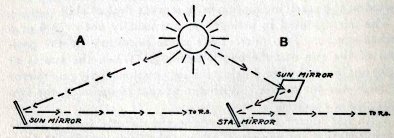 FIG. 11
53
GILBERT SIGNAL ENGINEERING
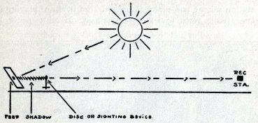 FIG. 12
receiving station. The station
mirror has a paper disc pasted on its face at the center. The
sun mirror is adjusted so that the whole of the station mirror
is reflected into it and the unsilvered spot and reflection of
paper disc accurately cover each other.
To sight flash on receiving station the reflection of the
distant station will be seen in station mirror and, by
adjusting this so the disc covers the reflection of distant
station, the flash will then be accurately in line.
Intercepting the Flashes. The method of intercepting flashes
in heliograph is either with the improved shutter with leaves
operated by a key or with a single shutter held in the hand.
In either case uniformity of movement should be maintained.
Because of the distances it is always advisable to count
slowly three times for a dot and six times for a dash.
Backgrounds. Dark backgrounds should be selected when possible
for heliographing, as signals can be more readily
distinguished.
To locate a distant station when its position is unknown, take
54 GILBERT BOY ENGINEERING
the station mirror and direct
it towards the horizon, playing it in slowly from right to
left several times. If no response is
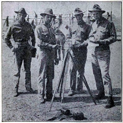 FIG. 13
U. S. Marines sending a
heliograph message.
FIG. 13
U. S. Marines sending a
heliograph message.
Courtesy of U. S. Marine Corps
received, direct it at a point
near the home station, and repeat this same process. As a
result of this method you will usually locate the station.
55 GILBERT SIGNAL
ENGINEERING
If position of each station is
known to the other, the station ready first will direct its
flash upon the distant station so that that station may be
able to adjust its flash to answer the signals.
In heliographing, the sun's movement has to be watched
carefully and adjustments made often. In the case of well
trained signalmen these adjustments can be made without
"breaking" a message. The heliograph is best operated by two
men.
Heliograph flashes are sometimes very hard on the eyes;
therefore it is always a good plan to smoke the lenses of the
telescope a little when its use is necessary.
THE ARDOIS SYSTEM
The Ardois System for night
signaling consists of a display of red and white incandescent
lamps which indicate the characters of the General Service
Code. The lamps are arranged in four units, each unit
consisting of a red and white lamp. The units are placed an
equal distance apart and usually suspended in a vertical
position from a mast, yardarm or staff, in which case
characters are read from top downward. When it is necessary to
place lamps horizontally they are read by sender from right to
left, and in case of receiver from left to right.
A red lamp indicates a dot and a white lamp a dash. The lamps
are operated by a keyboard.
The letters of General Service Code are made by a single
display; for example, A which is . - would be made
in the Ardois System by a display of the red light of the top
unit and the white light of the next unit below. The letter B
which is - . . .
would be expressed by a white light
from the top unit and the next three units below would be red.
Chart 8 gives alphabet for the Ardois System, also
conventional signals and numerals.
The numerals of General Service Code cannot be used in the
56 GILBERT BOY ENGINEERING
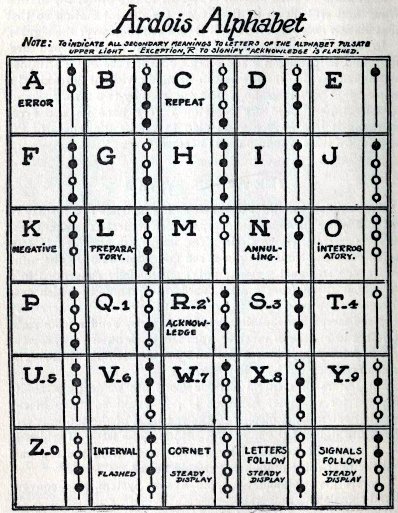 CHART 8
57
GILBERT SIGNAL ENGINEERING
Ardois system as the
expression is limited to four lamps. Therefore, numerals are
made by giving secondary meanings to letters of the alphabet
as shown on the chart.
To make a numeral, display the letter by which it is
indicated, and blink or pulsate the upper light.
In the case of letters which indicate conventional signals the
upper light is pulsated. The letter R is an exception to this.
When pulsated it signifies Number 2, when flashed it is the
conventional signal for "acknowledge."
The interval is made once to indicate end of word, twice for
end of sentence and three times for end of message. When
interval is displayed and upper lamp pulsated it is a
"Designator" signal.
The general call to attention is a steady display of cornet WWWW. The cornet is not
used, however, if call letter of station desired is known. In
answer to a call, display call letter of station, the calling
station then proceeds with message.
To indicate that an error has been made in the message make
"interval," the "error," then "interval" and then begin with
word in which error occurred.
The letter R flashed acknowledges the
receipt of a message.
When the Ardois System is in use, it is advisable to
extinguish all nearby lights which are liable to cause
confusion in signals.
The Ardois System is authorized for use by both Army and Navy.
THE VERY SYSTEM
The Very System of night
signaling is used by Army and Navy, its use is mainly confined
to signals of extreme importance or when distance is great.
The signals are made by firing red and green stars in the air
by means of a pistol which has a barrel similar in gauge to
58 GILBERT BOY ENGINEERING
the shotgun. The cartridges
firing the stars are like the shells of a shotgun.
This system is based on the dot and dash code, a red star
representing a dot and a green star a dash. This system,
however, is practical only for use with Army and Navy codes
and therefore is not of any service to a boy.
59 GILBERT SIGNAL ENGINEERING
Chapter VI
TELEGRAPHY, RADIO-TELEGRAPHY
AND TELEPHONY
All of these non-visual forms
of signaling are used by the signal corps of every modern
army. They are also the common means of communication in
everyday commercial life.
In all of the above methods of signaling the use of electrical
currents are necessary along with special instruments for
receiving and transmitting messages. The theory of electric
currents is a study in itself. This subject is covered in the
Gilbert Electrical Manual, and any boy wishing to acquire a
knowledge of electricity and to apply the theory to his
apparatus can do so by consulting Gilbert Manual of Telegraphy
or the Gilbert Book on Radio Engineering. The writer will
confine himself to the operative side of signaling, which
includes the code and proper form of handling messages over
these systems.
TELEGRAPHY
An American, Samuel F. Morse,
invented the first working telegraph instrument in year of
1835. This instrument was the recording or writing type, that
is, it made marks on strips of paper of dots and dashes which
could be spelled into a message. The recording instruments are
now obsolete and all telegraphy is conducted by sounding
instruments, which spell out messages by means of sharp
"clicks."
THE AMERICAN MORSE CODE
The American Morse Code is
used on all land telegraph lines and short cables. It is also
the official code of the Army for
60 GILBERT BOY ENGINEERING
AMERICAN MORSE CODE.
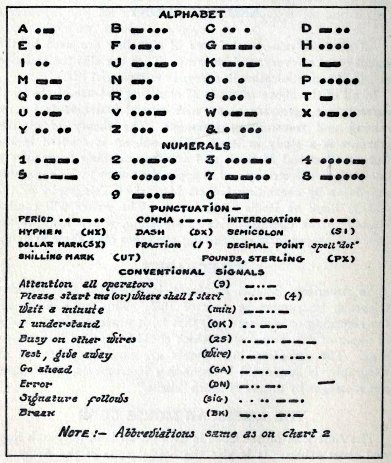 CHART 9
61
GILBERT SIGNAL ENGINEERING
electrical signaling on
military telegraph lines, short cables and field lines. This
code is written on Chart 9. Every signalist should familiarize
himself with this code and learn how it differs from the
General Service Code.
The beginner should thoroughly commit to memory the signs
representing the letters of the alphabet, the numerals and a
few of the principal punctuation marks. The remaining
characters can be learned afterwards as they are not needed by
a beginner.
The Morse Code is composed of seven elements :
(1) The dot; (2) the dash; (3) the long dash; (4) the space;
(5) the space between letters ; (6) the space between words
and (7) the space between sentences.
The dot is made by pressing the telegraph key down for the
smallest fraction of a second and then immediately releasing
it. The result on the sounding instrument is a "click-click"
very close together. The making of a dot involves time,
therefore the dash is equal to two dots and to make this the
key is held down accordingly. A "click click" sound results.
The long dash is equal to four dots, thus: "click click."
The ordinary space between elements of letters is equal in
time to a dot, between the letters themselves it is equal to
two dots. The word space is equal to three dots and the
sentence space is equal to six dots.
Correct Way of Using the Key.
The most successful manner of operating the telegraph key is
to let the forearm rest easily upon the table, grasping the
key as shown in Figure 14. The wrist should be well above the
table, the forefinger curved, but not held rigid. Let the
thumb rest on the edge of knob so that a slight control of the
upward motion is obtained. The raising spring should assist
the upward motion but should never be permitted to control it.
Avoid tapping upon the key. The
62 GILBERT BOY ENGINEERING
skilled operator will
manipulate it by a muscular action of wrist and ringers.
Elementary Practice of Code.
Constant practice of making dots with uniformity and precision
must first be acquired, then dashes, then grouping of dots and
dashes to form letters and words.
The beginner should commence by making letters slowly, giving
proper ratio of time to the elements of each letter. Speed
will come in time by persistent drill.
The most difficult letters of the code are C O R Z Y and S, termed the space
letters; and if spacing in these letters is not carefully
timed they will be readily confused with such letters as H I P and L.
The letters J and K, also numerals 9 and 7,
are difficult letters. Care should be given not to separate J into a space which would
result in a double N.
The usual tendency is to make an F too long and an L too short.
Practice transmitting from any miscellaneous manuscript at
hand. This will always test the skill of an operator.
RECEIVING TELEGRAPHY
Receiving is of course more difficult to acquire than sending
and is mastered best by having an experienced operator send
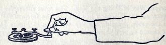 FIG. 14
63
GILBERT SIGNAL ENGINEERING
to the beginner slowly,
increasing the speed as learner becomes more proficient.
Proper Form of Transmission.
A telegraph message like all visual messages must be checked
by the sender. All words and figures written in the address,
body of message and the signature are counted. Of course To
and Sig. are not counted as they are only indicative terms
used by operator.
In counting the check of a telegraph message, whether in plain
English or code, groups or initial letters are counted as one
word.
Abbreviations for names of places, cities, towns and states
are counted as one word, as if written in full. This rule
applies also to any other abbreviations.
Figures, decimal points, bar of division and affixes to
numbers, such as d, st, nd, th and rd will each be counted as
a word.
RADIO-TELEGRAPHY
Radio-teiegraphy or wireless,
by which term it is more commonly known, was invented
by Marconi in 1901. Since that time there has been
developed many improvements, which make the transmission of
messages by wireless almost as practical as by telegraph lines
or cables.
Wireless messages are spelled out by use of the International
Morse or General Service Code (see Chart 1), the operator
using a key like that used in telegraphing. The result is
somewhat different from telegraphing, as wireless instruments
have a humming or buzzing sound instead of a "click." The
characters of the alphabet are made up of short and long
buzzes. The receiving is done through phones.
While wireless is under the control of the Navy in the United
States the government does not have exclusive use of it. A
great many commercial stations have been established and in
64 GILBERT BOY ENGINEERING
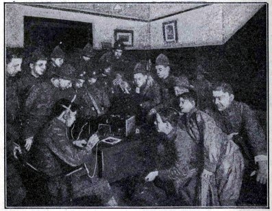 FIG. 15
Boy Scouts of Hartford,
Conn., learning the theory of wireless.
FIG. 15
Boy Scouts of Hartford,
Conn., learning the theory of wireless.
Courtesy of Boy Scouts of America
this country alone there are
thousands of boy experts using wireless, and enthusiasts are
being added to the list daily. Note : For conventional signals
other than in General Service Code see Gilbert Book on Radio
Engineering.
TELEPHONY
The most widely used of all
electrical signal systems is the telephone, invented by
Alexander G. Bell, an American. The telephone is so common in
our everyday life that most of us do not stop to consider the
interesting principles involved.
Color Charts
GILBERT BOY ENGINEERING
INDEX
Chart 10 Flags of the International Code
Chart 11 Ship Call Pennants Call Flags
Chart 12 Special Flags of the U. S. Navy
Chart 13 Personal Flags
Chart 14 Weather Signal Flags
GILBERT SIGNAL
ENGINEERING
FLAGS OF THE INTERNATIONAL CODE
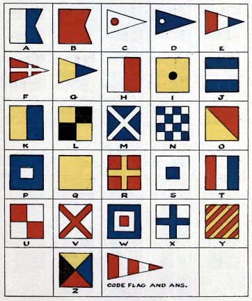 CHART 10
GILBERT
BOY ENGINEERING
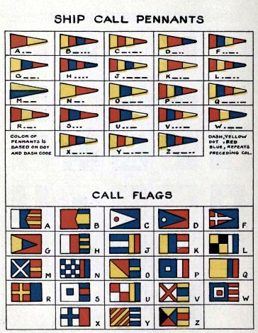 CHART 11
GILBERT SIGNAL
ENGINEERING
SPECIAL FLAGS OF THE U.S. NAVY
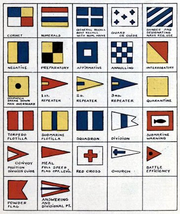 CHART 12
GILBERT
BOY ENGINEERING
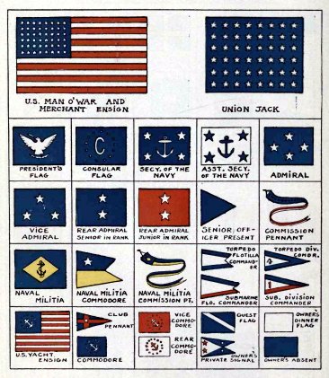 CHART 13
GILBERT
SIGNAL ENGINEERING
WEATHER SIGNAL FLAGS
 CHART 14
65
GILBERT SIGNAL ENGINEERING
In speaking, the vocal cords
cause air vibrations, which, falling upon the eardrum are
recognized by the auditory nerves as speech. When these
vibrations are transmitted into a telephone instrument, they
are caught by the sensitive diaphragm, changed into electrical
vibrations, carried along the telephone wire to the receiving
station and reproduced.
Note: See Gilbert "Sound Experiments" and Manual on Telephone.
THE TELEPHONE FOR SIGNAL PURPOSES
When signal stations are
connected by telephone, messages are of course sent by this
means, it being much more handy.
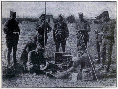 FIG. 16
U. S. Army Signal Corps
field radio station somewhere in France.
FIG. 16
U. S. Army Signal Corps
field radio station somewhere in France.
66
GILBERT BOY ENGINEERING
The difficulty arising in
telephonic messages is the confusion of certain letters of the
alphabet having like sounds when spoken by word of mouth.
To provide a ready means of distinguishing similar sounding
letters, a code of conventional signals is authorized for
military purposes and should be used especially when codes are
being sent. These conventional signals are as follows:
A Able
B Boy
C cast
D Dog
E Easy
F Fox
G George
H Have
I Item
J Jig
K King
L Love
M Mike |
N Nan
O Oboe
P Pup
Q Quack
R Rush
S Sail
T Tare
U Unit
V Vice
W Watch
X X-ray
Y Yoke
Z Zed |
To give an example of the
proper use of this code we will suppose an important message
is being telephoned to a station and the receiving operator
cannot clearly understand certain words such as directory, or
the word translation. To make these words clear the operator
would spell directory out slowly
Dog-Item-Rush-Easy-Cast-Tare-Oboe-Rush-Yoke. The word
translation would be spelled out likewise. From this code a
clear understanding would undoubtedly result.
67 GILBERT SIGNAL
ENGINEERING
THE SERVICE BUZZER
The Service Buzzer is a
portable piece of signal equipment especially adapted to the
needs of the Army Signal Corps. It can be readily attached to
either telephone or telegraph lines and used as a telephone or
for sending Morse or General Service Code telegraphic signals.
When service buzzer is used in the latter form the signals are
received in a telephone receiver in form of a high-pitched hum
very similar to wireless signals.
Signals have been exchanged between two buzzer outfits even
after wire connecting the stations has been cut in. The
instruments were, of course, grounded.
The mechanism of the buzzer is very simple, so simple in fact
that any boy can make a practical outfit for Field Service
Signaling by following the suggestions given in this book on
page 102.
68 GILBERT SIGNAL
ENGINEERING
Chapter VII
THE SIGNAL TOWER
The Tower of Babel served as a
rallying point and in all probabilities was the first signal
station. Later examples of old signal towers are those built
by the Chinese along the wall of China. Today, however, the
modern signalmen do not build such substantial towers, as the
up-to-date armies are mobile and consequently when a signal
tower is required a portable one or a hand-made affair, which
can be erected in a few minutes by field signal troops, is
used.
The boy signalist wanting to establish a visual station must
first select the site so it is perfectly in view of receiving
station and with a uniform background for all signals.
The distant
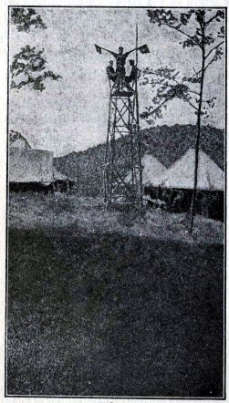 FIG. 17
Signal tower erected at a
boy Scout Camp.
FIG. 17
Signal tower erected at a
boy Scout Camp.
Courtesy of Boy Scouts of America Signals.
69
GILBERT SIGNAL ENGINEERING
station is the best judge of
the proper location and background for the signal tower.
In locating a military station secrecy is of vital importance,
and for this reason the tower is usually camouflaged by
shrubbery or erected behind foliage so the platform of tower
is barely exposed.
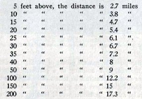
The following table gives distances of the visible horizon or
how far an object at sea level can be seen. When observer's
eye is :
It can readily be seen from
the above table that an observer whose eye is 25 feet above
sea level can distinguish an object at a distance of 6.1 miles
provided the object is at sea level. Now should the object
itself be elevated 15 feet its visibility would be increased
to 6.1 miles and 4.7 miles, equaling 10.8 miles.
To receive visual signals at the distances given above, a
telescope is used.
SUGGESTIONS FOR ERECTING A SIGNAL TOWER
The height necessary for
building a signal tower should be calculated according to
distance between points of communica-
70 GILBERT BOY ENGINEERING
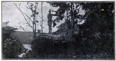 FIG. 18
A natural point of vantage
for signaling.
FIG. 18
A natural point of vantage
for signaling.
Courtesy of Boy Scouts of America
tion. When possible, natural
points of vantage should be used, such as the roof of a
building or a platform built in a tree. Sometimes several
trees can be found close together which can be connected by
stringers and a platform laid around, to which a rail can be
added. A ladder would lead up to the staging to complete the
arrangement.
Where no natural supports can be found, it will be necessary
to build a tower. A substantial tower can be erected by using
either three or four uprights for supporting the platform. The
uprights can be made of finished lumber, using 2x4 pieces or
heavier ones, depending on height of tower wanted.
The drawing on page 71 suggests a tower made of three selected
trees cut to lengths of 18 feet. These are placed in the
ground about 1 l /2 or 2 feet, the arrangement of
placing being triangular and 8 feet apart. The uprights are
leaned in at the top and tied 4 feet apart, on which a
platform is laid which will accommodate two signalmen. The
platform can be made of
71 GILBERT SIGNAL ENGINEERING
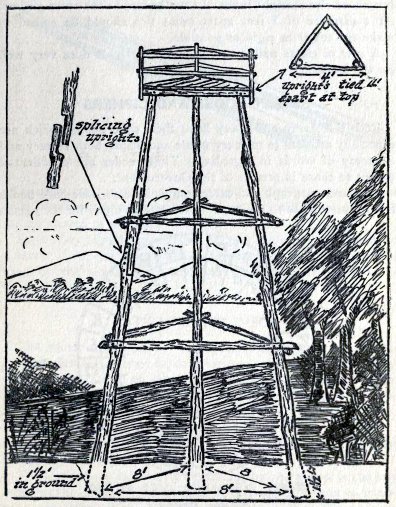 FIG. 19
Illustrating method of
constructing signal tower
FIG. 19
Illustrating method of
constructing signal tower
72
GILBERT BOY ENGINEERING
boards or else straight limbs
of trees spiked to the cross girders. At a distance of 5 feet
apart cross ties should be spiked to make the tower as rigid
as possible.
A row of cleats nailed to one of the uprights does very well
for the ladder.
SECRET CODES AND CIPHERS
Both the Army and Navy have
their code books, which are especially adapted to military
needs and insure both secrecy and economy of words in
signaling. These codes are confidential except to those in
service of the Government.
The land telegraph and cable companies also issue code books
from time to time to their customers, not so much for the
reason
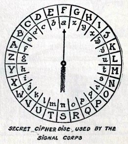 FIG. 20
73
GILBERT SIGNAL ENGINEERING
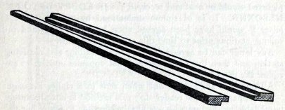 FIG. 21
of secrecy, as for economical
benefit of the messages. These code books can sometimes be
obtained and will serve very well for all classes of signals.
So the boy signalman will not be handicapped for the want of a
secret code, the writer will suggest the cipher disc which is
used by the signal corps and another improvised method of
using the cipher.
THE CIPHER DISC
The cipher disc used by the
signal corps is a simple but ingenious device pictured in
drawing on opposite page. It consists of two circles of
cardboard, one smaller than the other. These are joined at
center so as to revolve. The inner circle is lettered around
the edge with small letters and the outer circle with capital
letters of the alphabet.
The alphabet reads from right to left on outer circle and left
to right on the inner circle.
The letter A on inner circle indicated by the arrow is the key
letter to the cipher. The purpose of this cipher is only to
transpose one letter of the alphabet for another, thus the
message WE BREAK CAMP AT
SUNRISE when read from the disc
74 GILBERT BOY ENGINEERING
pictured would be sent and
received as: JB EOBFV DFTQ
FM NLSOXNB. It is of course understood by reader that
the letter F would have been agreed upon by the sending and
receiving stations prior to time this message was sent.
Any letter can be agreed upon between sending and receiving
station and then the key letter A is set opposite on disc to
encipher the message.
All numbers are spelled out when sent in a cipher message.
It is apparent to the reader that this method is not
absolutely unreadable to any one who would take the time to
figure out the key; however, when used in connection with a
code, it can be made much more complicated to any one desiring
to read your message.
The above method of sending cipher could be used with the
General Service Code which was in existence prior to the
adoption of the International Code of dots and dashes.
The old General Service Code is written as follows :
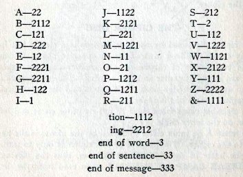
75
GILBERT SIGNAL ENGINEERING
The foregoing code is used
with the various signal systems as follows :
Wigwag or single flag
- one would be to right and two to left, three would be
expressed by the front motion.
Ardois System - one
would be red light and two white light, a space would be made
for end of word, etc.
Sound System, by whistle,
bell and foghorn - one would be indicated by a short
blast or taps and three likewise.
Telegraph, Wireless and Flash
Light System - one would be made by one click, buzz
or flash, two by two clicks, buzzes or flashes and three made
in same way using three.
HOW TO MAKE A CIPHER OUTFIT
A practical, yet simple cipher
can be made by first obtaining several pieces of ordinary flat
picture moulding like those shown in Figure 21. These pieces
will slide parallel to each other; one piece should be at
least 14 or 15 inches in length, while the other can be just
half that length.
Next take white ruled paper and paste along flat surfaces of
moulding, the ruling or lines of paper should be about 1/4
inch apart.
Fifty-two spaces are necessary for the long piece and the
alphabet is written twice, backwards, in small letters,
starting from top as shown in Figure 22, these letters are
numbered from 1 to 52.
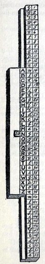 FIG. 22
 The
Science Notebook
The
Science Notebook