101 GILBERT SIGNAL ENGINEERING
No. 1 of Chart 16 shows the
proper way to lay out a wigwag flag. The cloth can be tacked
to any flat surface and, with a ruler and pencil, a square can
be marked off the exact size wanted. Lines can then be drawn
from corner to corner as shown. This serves to help;
get the square in the exact center. The cloth can then be
cui around the dotted lines, which should be about 1/4 or
1/2 inch. from the edge of the flag. This gives enough
margin for hemming . The next step is to turn down the
edges of flag and pin. A selvedged edge can then be made by
hemming on a sewing machine or stitching by hand. After this
is done another small piece of cloth of opposite color is
marked off as pictured in No. 2. The size of square being same
as the square in center of flag. The smaller piece of cloth is
then cut around on the dotted lines and hemmed around the
edge, after which it is placed over the square of the larger
piece of cloth and sewed on. Be careful to stitch as close to
edge as possible. After this the flag can be turned over and
cut out on inside of stitching with a pair of scissors. This
brings the square through and makes flag the same on both
sides. The flag is now complete except for a staff and the
fastenings necessary.
Ties can be sewed on flag as shown in No. 3, using flat
binding tape. Three ties will be enough one in center and one
at each end, as seen in No. 4 on the completed flag. For a
staff a bamboo fishing pole can be used or any round pole of
3/4 to 1 inch in diameter.
No. 5 suggests several ways of making a jointed pole if one is
wanted to make flag staff convenient to carry on a hike.
THE WIGWAG DISC
No. 6 suggests a disc for
wigwagging. The disc can be either cut out of a piece of tin
or heavy cardboard, painted in colors black and white or red
and white and then tacked to a
102 GILBERT BOY ENGINEERING
slender stick or pole. This
piece of signal apparatus is easily made and has the advantage
over the flag on a windy day as flag is very apt to foul while
the disc is not open to this objection.
SEMAPHORE FLAG MAKING
Semaphore flags can be made
exactly like wigwag flags except for size, which vary from the
10 and 15-inch sizes used in Navy to 24-inch size which
is the largest used by the Army.
For all around semaphore signaling the 12 to 18-inch size will
be found most adaptable. The flags are always made square in
shape and usually of a design like the wigwag flags, with
square center or the diagonal type illustrated. (No. 8.)
No. 7 shows the way to mark off cloth for cutting out the
diagonal flag.
The ties for fastening flag to stick can be made the same way
as in the case of the wigwag, but need not be as strong. The
darkest portion of flag goes next to stick and the stick
should be only long enough to allow a hand hold below the
flag. The stick can be notched to keep ties in place ; or
another way which makes a neat effect is to make eyelets as
shown in No. 9. This is done by shaping the eyelets out of a
piece of copper wire, flattening the ends and binding them to
the stick with fine wire or heavy thread, after which a coat
of varnish, if added, will put on the finished appearance.
HOW TO MAKE A FIELD BUZZER OUTFIT
The field buzzer is an
instrument used by Boy Scouts and armies for sending and
receiving signals between temporary stations. It is strictly a
portable instrument. The one used by the United States Army
can be used for many kinds of signaling. It will work as a
telephone or as a telegraph. Of course it is used as a
telephone whenever possible ; but when the connecting lines
are broken, it is possible to use the sets as tele-
103 GILBERT SIGNAL
ENGINEERING
graph stations, and messages
are sent and received in the form of a high pitched hum very
much like that of a radio signal.
In actual field use, these messages have been sent and
received when the lines were cut off but both ends of the line
slightly grounded. It is not hard to make an instrument
similar to the United States Service Buzzer which will give
the Gilbert Signal Engineers lots of sport as well as practice
in telephone and telegraph work. This amateur set will not, of
course, be so elaborate as the army set, because the latter is
made for use in all sorts of weather, in all sorts of places.
But for practice work, the little sets described below will
serve you just as well and will be cheaper and easier to
build.
TELEGRAPH BUZZER
This instrument can not be
used as a telephone set, but can send and receive Morse and
Continental Code telegraph messages.
SERVICE BUZZER
Parts Required
1. Panel - This should be about 1/8 of an inch
thick and can be made of hard black rubber, black fibre, or
even thin wood painted or stained to make it look well. This
panel should be 6 inches long and 3 1/2 inches wide.
2. Battery - Purchase
five flash light batteries and connect them in series. The
batteries used in the set described here measure 1 3/8 wide,
11/16 inches thick and 2 1/4 inches long. But batteries of
other size can be used if necessary, and the only change in
the set required will be in the wooden box enclosing the set
and in the size of the panel.
3. Key or Button -
For this set an ordinary doorbell push button will do very
well.
4. Telephone Receiver
- Purchase a 75 ohm telephone receiver of the watch case type.
104 GILBERT BOY ENGINEERING
PANEL SHOWING COMPLETE ASSEMBLY
CONNECTING WIRES SHOWN DOTTED
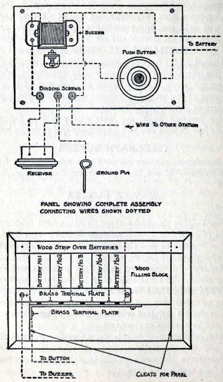 FIG. 28
105
GILBERT SIGNAL ENGINEERING 105
5. Vibrator and Vibrator Coil - You can buy a
buzzer such as is used for sending practice in wireless
telegraphy, or, if you prefer to make one yourself, you will
find the following instruction helpful.
Cut two cardboard or fibre discs; these should be about 24
inches in diameter. Put a hole through the center 3/16 inches
in diameter and two small holes for the wire to pass through
as near the edge as possible and on opposite side of the large
center hole. These small holes can be made with a small nail
or an awl. (See Figure 29.)
Make two supports for the buzzer, using 1/16 inch steel and a
vibrator of springy steel about 1/64 of an inch thick.
Place an 8-32 round head steel machine screw 1 1/8
inches long through one of the supports and washers, holding
the latter tightly against the screw head. Wrap six or seven
layers of writing paper around the body of the screw. Make the
width of this paper 24 of an inch. Place the other washer on
the screw and tighten it against the end of the paper wrapper,
by means of a steel nut. Wind over the paper 25 feet of No. 24
B&S Gauge copper wire insulated either with enamel or
cotton.
Start this winding by pushing a beginning of the wire through
one of the small holes in the end washer, leaving about 2 l /
2 inches of wire sticking through the hole for a connecting
lead. When the coil is complete, stick the end through one of
the other small holes and your magnet is complete.
Next you will need a support for the adjusting screw, which
should be of brass 8-32 and about l/2 inch long. This is
locked in place by an adjusting nut.
6. Box - This should be a well-made box with a hinged cover
and clasp. (See Figure 30.) Make the inside dimensions of the
box 6 inches long, 3 l/2 inches wide and 2 inches deep. The
cover should be 6 inches by 3 l/2 inches by 1 inch deep. If
you plan to
106 GILBERT BOY ENGINEERING
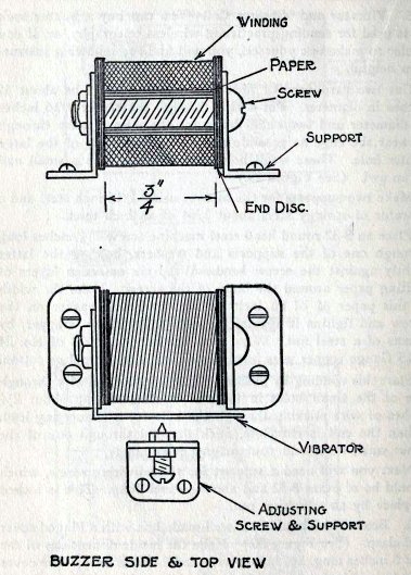 FIG. 29
107
GILBERT SIGNAL ENGINEERING
use the buzzer on hikes, it
will be well to put a carrying strap of leather or webbing on
the box.
The batteries should be held in place by end blocks of wood
and also by the two brass terminal strips shown in Figure 28.
The battery terminals should be placed so they make good
contact with these brass strips so that the first battery on
the right
BOX COMPLETE.
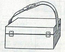 FIG. 30
has the outside terminal
against the upper strip, the next will have the outside
terminal against the lower strip. Alternate these connections
until all the batteries are in place.
Make the connections as shown in the diagram (Figure 28),
fasten the panel in place, attach the telephone receiver to
the binding screw and the instrument is ready for use. It will
be a great help if you make an iron pin to push into the
ground for one side of the line circuit. The other side should
be a copper wire at least as large as No. 24 B&S Gauge.
BUZZER AND PHONE COMBINED
If in the above instrument we
had used a telephone receiver connected, as shown in the next
diagram (Figure 31), with this
108 GILBERT BOY ENGINEERING
circuit when the key is
closed, a single click would have been heard in the receiver.
If the key is held down, no further sound will be heard unless
some one speaks into the transmitter. The set will then act as
a telephone. We will not take the time here to explain the
telephone theory. It requires a book by itself.
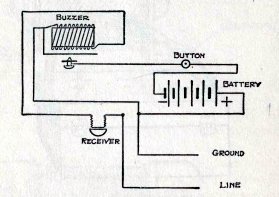 FIG. 31
Now we can combine the
telegraph and telephone instruments in one by the addition of
a second push button or key and a transmitter. Study the
connection diagrams shown (Figures 32 and 33) and you will
have very little trouble in understanding how to build this
set.
When you wish to use this outfit as a telephone, you press Key
No. 2, holding it closed. A current will then flow from the +
side of the battery to the ground, from the ground it will
pass through the grounded side of the listening station,
around the buzzer winding, through the listening station
receiver to the line back to the sending station, through the
sending station receiver to the telephone transmitter, from
the transmitter to Key No. 2 and from Key No. 2 to the
battery, thus completing
109 GILBERT SIGNAL
ENGINEERING
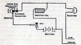 FIG. 32
the Circuit. Note the whole
battery is not used for this circuit but only two batteries
are connected by a tap for the telephone use.
When the speaker at the sending station talks into the
transmitter, his voice sets the little granules of carbon in
motion, thus varying the resistance of the circuit. This
causes the current to
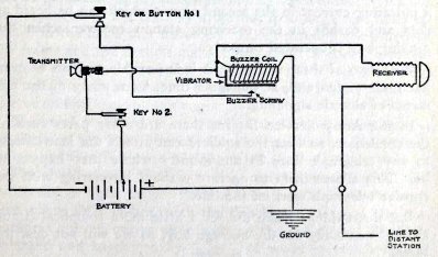 FIG. 33
110
GILBERT BOY ENGINEERING
fluctuate, causing the magnet
in the receiver to vibrate the diaphragm for every tone the
sender utters. This is heard as a telephone message by the
listener at the receiving end.
To use the telegraph circuit, Key No. 1 is pressed. When it
closes the circuit, the current flows from the positive side
of the battery to the buzzer coil, to the vibrator. From the
vibrator it passes to the brass contact screw, but at this
point the circuit is rapidly opened and closed due to the
action of the magnet and
vibrator. From the contact screw, the current passes to the
Key No. 1, from the key back to the negative side of the
entire battery.
But in addition to this there is also a current flowing from
the ground to the receiving station ground, through the
receiving station buzzer coil, from the coil to the receiving
station telephone receiver where a high pitched hum is heard,
from the receiver to the line back to the line side of the
sending instrument receiver to sending station buzzer coil and
back to the ground.
When the sending station buzzer starts vibrating, it sets up a
pulsating current in the second circuit which can be heard as
dots and dashes in the receiving station receiver when the
sending key is operated properly.
With two of these instruments it is possible for two boys to
have lots of fun and, at the same time, learn many of the
elements of electric signaling.
In the Army Service Buzzer there are other parts such as the
condenser, so that the soldiers can attach the instruments to
any telegraph lines in the country where they happen to be.
This allows them to operate without interfering with the
regular telegraph work of the line.
But these things make the set a little more complicated and
are not necessary for the average boy, so we will not describe
them.
111 GILBERT SIGNAL
ENGINEERING
HOW TO MAKE A HELIOGRAPH
Before trying to make the
heliograph outfit illustrated on Chart 17 read over carefully
the theory of heliographing in Chapter V, page 50, and with
these principles thoroughly fixed in your mind the making and
operating of the heliograph will be very easy.
To make heliograph as shown the station mirror and the two
diaphragms L (Nos. 2 and 3) are supported on a tripod, made by
using a 2x4 or 4x4 inch upright. This can be sharpened and
driven in the ground about 1 1/2 or 2 feet, after which a 2x4
inch piece 6 1/2 feet long can be fastened through the flat
side at the center to the post by a large screw. This will
allow the instrument to turn so as to face in any direction
desired.
The station mirror can be made as pictured by using a plate
glass mirror 4 inches square. The mirror is set in a frame
made of picture moulding. The framed mirror is then mounted in
a U-shaped easel. The easel can be made out of 1x1 inch lumber
and strengthened by using small angle irons at corners. (These
can be purchased at any hardware store.) The mirror frame can
be suspended in the easel by attaching it to large size nails
inserted in the holes that have been drilled through the
center of the frame and the upright ends of the easel. A
spring arrangement is then placed on each side of the mirror
frame between the uprights of the easel. This can be worked
out so that the mirror will set rigid at any angle.
The easel is bolted to one end of the tripod, using several
washers on the bolt, between the 2x4 and easel. The station
mirror can then be turned to right or left.
The diaphragms, Nos. 2 and 3, can be made out of tin,
cardboard or light wood. Both of them can be made the same
size, about 8x12 inches, with the 8-inch side at top. The
diaphragms are cut out so as to slide on the 2x4 piece. They
are balanced and supported by a piece of wood to which several
112 GILBERT BOY ENGINEERING
HOW TO MAKE A HELIOGRAPH
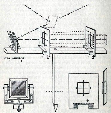 CHART 17
113
GILBERT SIGNAL ENGINEERING
blocks are nailed on each side
as shown. The diaphragm is of course tacked to the wood
supports; this allows the completed diaphragm to slide on the
2x4 piece of the tripod.
The diaphragm shown in No. 2 has a square hole 3x3 inches at
center, with cross wires. That shown in No. 3 has a square
hole 2x2 inches, with cross wires or thread.
In making the diaphragms a great deal of care must be given to
obtaining the right size hole in each and also that in the
center of the station mirror. (Make the hole in the exact
center of station mirror by scratching off a little of the
silver.) The cross wires in each diaphragm must be exactly in
line.
HOW TO OPERATE
The advantage of this type of heliograph over the open mirror
type is that it reduces the beam of light down to a direct
flash by means of the two diaphragms. The result of which is
shown on Chart 17 by the dotted line which represents the
straight course of the rays coming from the second diaphragm
(No. 3).
The first diaphragm should be placed about 1 foot from the
station and the second diaphragm (No. 3) about 3 l /2 to 4 1/2
feet distant from the first; as both slide they can be adjusted
easily to the proper distance.
By lining up the receiving station through peep hole and cross
wires of both of the diaphragms and the station mirror angled so
as to catch the sun's rays, the apparatus is ready to send the
message.
The flashes can be intercepted by using a piece of tin or wood
about 12x12 inches square, to which several pieces of 1x1 inch
wood can be nailed, as pictured at lower right hand corner of
Chart 17. This gives a good hand, hold and perfect control of
your shutter.
114 GILBERT BOY ENGINEERING
An additional mirror will be
necessary should the sun be behind the sender. The extra
mirror can be held by another boy in this case so as to
deflect the sun's rays into the station mirror.
A little practice will be necessary to get accustomed to the
adjustment required when the angle which the sun's rays make
with the mirror changes at different times during the day.
When the knack of arranging the mirror is acquired you will
have no trouble in sending a message up to twenty-five miles,
if that distance is required with this outfit.
HOW TO MAKE
A SEMAPHORE AND BLINKER
The semaphore at center of
Chart 18 needs little explanation as it is simply two cross
arms with paddles which can be painted in conspicuous
alternating colors so as to be readable at a distance.
The post which carries the semaphore arms can be any height
desired. The arms to which paddles are nailed should be made
of 1x1 inch light pine wood and the paddles about 1/4 or
3/8 inches thick by 2 1/2 feet in length and 6 to 8 inches in
width.
The semaphore arms are bolted or nailed below the other arms
so as to fold back to post when not in use. This extra arm
indicates to receiving station the sender's right or left.
Messages are transmitted by pulling the semaphore wings up by
means of the cord to a position at right angles to the upright
post and then dropping same immediately to a position parallel
to and in back of the post.
The, right wing when pulled up to the position mentioned will
indicate the dot of the General Service Code and the left wing
will indicate the dash. The end of word can be indicated by
raising both arms at same time and the end of sentence by
swinging the arms a little.
115 GILBERT SIGNAL ENGINEERING
MAKING A SEMAPHORE BLINKER
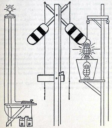 CHART 18
116
GILBERT BOY ENGINEERING
THE BLINKERS
Two types of blinker lights
for sending messages by General Service Code are pictured on
Chart 18.
The blinker at the right on the chart is made with a lantern
and operated by a cord passing over two small pulleys. The
lantern is so suspended as to make it possible to drop it in a
bucket, which of course "douses the glim." By pulling the
lantern up and letting it drop back into the bucket, a dot or
dash can be made by timing the length of lantern's exposure.
The blinker on the left of Chart 18 is operated electrically
by using a telegraph key. A miniature receptacle can be
purchased at any electrical shop. This can be mounted on a
wooden block and nailed to top of a pole or in fact any other
suitable place. A small 2 or 3 candle power light can be used
in the receptacle for the light. (A 3 candle power light is
good for a distance of 3/4 of a mile without the use of
binoculars.) One light copper insulated wire is run from one
terminal of receptacle to the dry cell batteries, which are
connected in series. Another wire is run down from the other
terminal of receptacle to the key and then to the batteries.
Two dry cell batteries will be strong enough to cause a 3
candle power lamp to work satisfactorily.
MEMORANDUM PAGES &
ADVERTISEMENTS
 The
Science Notebook
The
Science Notebook