TITLE
2
INTRODUCTION
NOWADAYS there are so many
very interesting things going on all about us that very often
we are likely to overlook things which have an important
bearing on our everyday life. Small things which we are so
used to having around that we never stop to think what they
really mean to us.
For instance water. It's nice to drink, and bathe in
but very few of us ever stop to consider the innumerable uses
water is put to and what a great influence it has on many
things we do. Most of us are satisfied to turn on the faucet
and get our water in that way. If something is wrong and the
water doesn't come from the faucet we call up the plumber, but
we do not realize what has gone wrong simply because we do not
understand how a house is piped for water nor do we understand
why water gets into the pipes, etc.
Then air - another thing which we couldn't live
without and yet few appreciate its value. Air and water give
us tremendous results as pneumatic and hydraulic pressure. A
knowledge of these great forces which most boys are so
familiar with and still do not understand thoroughly will put
you up far ahead of your boy friends. Most boys take things
too much for granted; it is the clever boy Who digs into
things and find out the reasons.
It is the earnest hope of the authors of this book
that the boys who read it will have a better understanding of
water and air, how they are used, and what they mean to us.
Sincerely yours,

COPYRIGHTED, 1920, BY A. C. GlLBERT
NEW HAVEN, CONN.
HYDRAULIC AND PNEUMATIC ENGINEERING
3
INDEX TO ILLUSTRATIONS
HYDRAULIC APPLIANCES
City Water Supply Figs. 1, 2 Pages 5, 6
Private Water Supply Figs. 3, 4 Pages 7, 8
Attic Tank System Figs. 7, 8 Page 10
Water Supply From Spring Figs. 11, 12 Page 12
Pneumatic Tank Figs. 22, 23 Page 16
Siphon Over Hill Figs. 31, 33, 35 Pages 21, 22
Lift Pump Figs. 62, 63 Page 43
Force Pump Fig. 65 Page 45
Hydraulic Press Figs. 68A, 73 Pages 48, 52
Hydraulic Elevator Figs. 68B, 75 Pages 48, 53
Hydraulic Lift Lock Figs. 68C, 79, 81, 82 Pages 48,
55, 58
Depth Bomb Fig. 90 Page 66
Torpedo Figs. 91, 92 Page 67
Submarine Fig. 93 Page 68
Battleship Fig. 98 Page 72
Raising Sunken Ships Figs. 105, 106, 108 Pages 79, 80,
81
Floating Dry Docks Figs. 109, 110 Pages 82, 83
Air Lock in Pipes Figs. 120, 121 Pages 90, 91
PNEUMATIC APPLIANCES
Magdeburg Hemispheres Fig. 122 Page 93
Barometer Figs. 129, 130 Page 99
Air Zones Fig. 131 Page 100
Altitude Gauge Fig. 132 Page 101
Air Lift Pump Figs. 139, 140 Pages 105, 106
Balloons Figs. 144, 145 Pages 110, 111
Helium Balloons Fig. 146 Page 112
Air Brakes Figs. 156, 157 Pages 121, 122
Flame Thrower Fig. 158 Page 123
Fire Extinguisher Fig. 160 Page 124
Bicycle Pumps Fig. 165 Page 128
Air Compressor Fig. 167 Page 130
Sand Blast Fig. 168 Page 130
Pneumatic Paint Brush Fig. 170 Page 132
Diving Bell Figs. 172, 173 Pages 133, 134
Pneumatic Caisson Figs. 176, 177 Page 137
Torpedo Discharge Tube Fig. 178 Page 138
Air From Sea Water Fig. 180 Page 140
CHART OF
HYDRAULIC AND PNEUMATIC SEPARATE PARTS
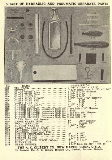
Hydraulic and Pneumatic
Engineering
Hydraulic Engineering is the Engineering which deals
with water and other liquids.
Pneumatic Engineering is the Engineering which deals
with air and other gases.
WATER SUPPLY
Boys, have you running water in your homes? If so, do
you know how it gets there? You will show how with
this Engineering set.
If you live in a city, your running water is supplied
in one of three ways: first, it is pumped
into a standpipe or reservoir; second, it is
brought from a distant lake or stream at a higher level; or
third, it is pumped directly into the city mains.
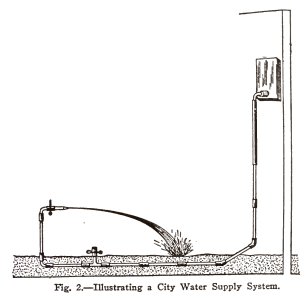
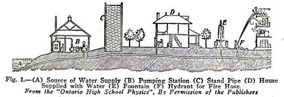
The standpipe method is illustrated in Fig. 1. The
water is pumped by means of a force pump B from a river or
lake A into a standpipe C, from which it runs by gravity
through the under-ground pipes or mains to the houses D,
fountains E and hydrants F. This system is used in towns and
small cities situated in a flat region, because it is the
cheapest means of getting the water above the level of the
highest house faucet in the town.
If the town is situated near a hill, the usual
practice is to build a large cement lined reservoir on the
hill and to pump the water into this instead of into a
standpipe. In either case the water runs by gravity through
the mains and submains to the houses, hydrants, etc.
If the city is very large, the usual practice is to
bring the water from a lake or stream at a higher level. New
York is supplied with water in this way.
See page 145 for diagram of apparatus needed to
perform experiments in this book.
6 HYDRAULIC AND
PNEUMATIC ENGINEERING
If the city is very large and if an elevated lake or
stream cannot be found within a reasonable distance, the usual
practice is to pump the water directly into the city mains,
from the nearest river or lake.
In all cases the greatest care is taken to see that
the water is pure. The land bordering the elevated lake or
stream is kept free from all sources of contamination and in
addition the water is filtered. If the water is pumped from a
lake, the intake pipe is run out into the lake for a long
distance, to get the purest water and in addition the water is
filtered. If the water is pumped from a river near the city,
it is taken in above the city and is filtered.
EXPERIMENT No. 1
To make and operate a city
water supply system in which the water comes from a standpipe,
reservoir or lake.
Arrange the apparatus as shown in Fig. 2 and bury the mains an
inch or two in sand or earth if convenient. Allow the water to
run from the house faucet, that is, the nozzle. Attach an
elbow, hose, and nozzle to the hydrant, that is, the coupling,
and allow the water to run.
You have here shown how the water runs from a
standpipe, reservoir, or elevated lake, through the mains to
the hydrants in the streets of a city and to the faucets in
the houses.
NOTE 1. When
you wish to insert a glass tube into a rubber stopper or
coupling always place the stopper or coupling in a glass of
water to wet the rubber on the inside, then insert the glass
tubes with a twisting motion. Always hold the glass tube near
the end you are inserting into the rubber stopper or coupling.
Thi is very important, because, if you hold the tube too far
back, you may break it.
HYDRAULIC AND PNEUMATIC
ENGINEERING 7
NOTE 2. When
you are through with an experiment always take the apparatus
apart. Be sure particularly not to leave a glass tube in a
rubber coupling or stopper because the tube will stretch the
rubber permanently and the glass and rubber will stick
together.
NOTE 3. Make
the experiments out of doors, in the garage, in the basement,
or in the bathroom. Keep all unused tubes in the box where you
will not step on them.
NOTE 4. Let
Dad enjoy this with you; he was a boy once, and will enjoy the
fun as much as you do.
If you live in the country, or in a town where there
is no public water supply system, and if you have running
water in your home, you must have a private water supply
system of some kind.
8 HYDRAULIC AND PNEUMATIC
ENGINEERING
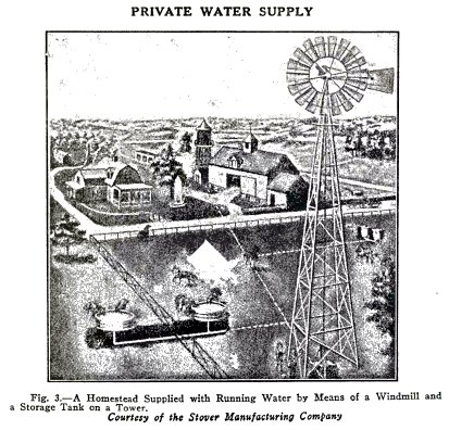
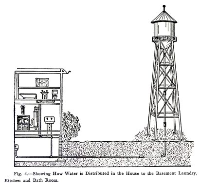
In the system shown in Fig. 3 the water is pumped by
means of a windmill and force pump into a tank on a tower and
from this it runs by gravity to the house, the fountain, and
the stable. The drawing in Fig. 4 shows how the water from the
tank is distributed to the laundry, kitchen, and bathroom of
the house.
EXPERIMENT No. 2
To
make and operate a private water supply system in which the
water is stored in a tank on a tower.
Arrange the apparatus as in Fig. 5. Hold the nozzles
horizontal and open them one at a time, then together. Is the
stream from the lower nozzle longer than that from the upper?
Arrange the apparatus as shown in Fig. 6. Open the
nozzles when horizontal and at the same level Are the streams
of equal lengths?
HYDRAULIC AND PNEUMATIC
ENGINEERING 9
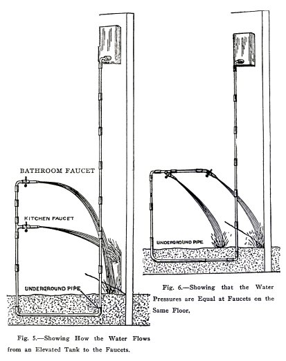
You have shown here how the water runs from a tank on
a tower through the vertical pipe and underground pipe to the
faucets in the house. You have shown also that the pressure is
greater at a lower faucet than at an upper faucet and that the
pressures are equal at faucets on the same level.
10 HYDRAULIC AND
PNEUMATIC ENGINEERING
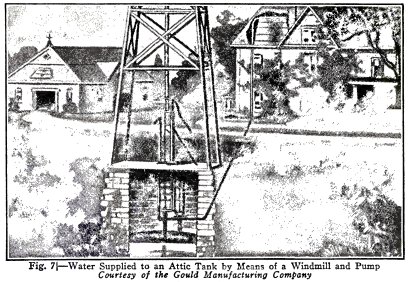
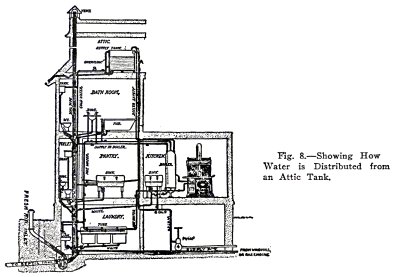
In Fig. 7 the water is pumped by a wind-mill and force
pump into a tank in the attic of the house, and from there it
runs by gravity to the various house fixtures as shown in Fig.
8. The force pump is often driven by a gas engine instead of
by a windmill. The hand pump (4) Fig. 8 is used only when the
gas engine or windmill is out of order.
HYDRAULIC AND PNEUMATIC
ENGINEERING 11
EXPERIMENT No. 3
To
make and operate a private water supply system in which the
water is stored in an attic tank.
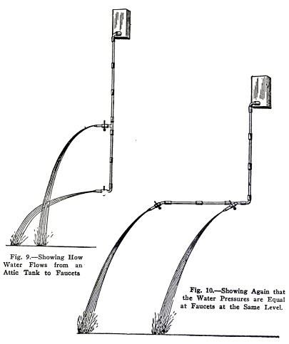
Arrange the apparatus as in Fig. 9. Hold the nozzles
horizontal one above the other and open them together. Is the
longer stream from the lower nozzle? That is, is the greater
pressure at the lower faucet?
Arrange the apparatus as in Fig. 10. Hold the nozzles
horizontal and open them together. Are the streams of the same
length? That is, are the pressures equal?
You have shown here again that the greater pressure is
at the lower faucet and that the pressures are equal at
faucets on the same level.
12 HYDRAULIC AND PNEUMATIC
ENGINEERING
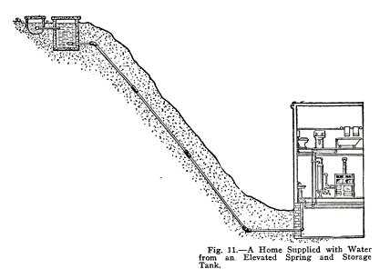
In Fig. 11 the water from an elevated spring runs by
gravity into a storage tank and then through an underground
pipe to the house fixtures.
EXPERIMENT No. 4
To
show how water is brought from an elevated lake or
spring.
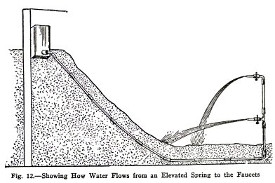
Arrange the apparatus as shown in Fig. 12. Place the
tank on a mound of sand or earth and bury the underground pipe
to a depth of one or two inches. Allow the water to run.
You have shown here how the water is brought to a city
from an elevated lake or stream, or how it is brought to a
private house from an elevated spring.
HYDRAULIC AND PNEUMATIC
ENGINEERING 13
A NAVAL BATTLE
GAME No. 1
You can invent all sorts of games to be played with
this Engineering set. The Naval Battle is one and it is an
excellent game for a hot day.
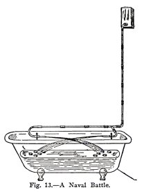
Float a number of tin cans, tumblers, or cups on water in a
bath tub, or in a wash tub, Fig. 13. Arrange the apparatus as
shown. Each player directs his stream against the warships of
the other, and the winner is the one who first sinks all the
enemy war ships.
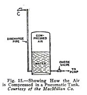
PNEUMATIC TANK SYSTEM OF WATER SUPPLY
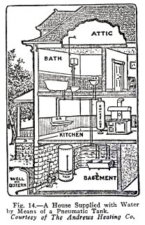
The pneumatic tank system of water supply is
illustrated in Fig. 14. The water is pumped into the
bottom of an air-tight steel tank and compresses the air
in the tank to smaller volume at the top. This compressed
air then forces the water out through the discharge
pipe at the bottom of the tank and lifts it to the faucets
in the rooms above. The interior of the tank is
represented in Fig. 15. The compressed air at the top of
the tank forces water up the discharge pipe when any
faucet C is opened.
14 HYDRAULIC AND PNEUMATIC
ENGINEERING
EXPERIMENT No. 5
To make and operate a pneumatic
tank.
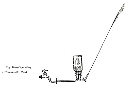
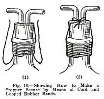
Arrange the apparatus as shown in Fig. 16. It is
necessary to fasten the stopper in the bottle very securely.
Do this as follows: Insert two elbows into the two-hole rubber
stopper and twist the stopper firmly into the neck of the
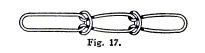
bottle. Next loop three strong rubber bands together as shown
in Fig. 17, pass a stout cord over the stopper and wind the
stretched rubber bands around the neck and cord. Now slip the
last end of the bands under the last winding to hold it, (1)
Fig. 18, then tie the ends of the cord up over the stopper,
(2) Fig. 18, and you will find that the stopper is very
secure.
The stretched rubber bands make a very secure tie
because each Stretched winding grips the cord. You will use
this tie often in your experiments.
Note - You
can use the tee and one-hole stopper instead of the elbows and
two-hole stopper if you prefer.
HYDRAULIC AND PNEUMATIC
ENGINEERING 15
Now: open the clip on the hose, open the faucet Fig.
16, slightly, run water into the bottle until it is half full,
close the faucet, close the clip on the hose, remove stopper
from faucet, point the nozzle upward, and open the clip on the
nozzle.
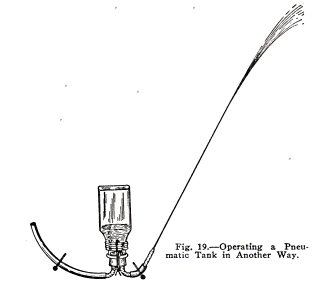
Does the compressed air force the water out with
surprising force? If you have no water faucet handy,
illustrate the pneumatic tank as shown in Fig. 19. Fill the
bottle half full of water, tie the stopper in place, force air
in with your mouth or with a bicycle pump, and observe the
stream as before.
Find a larger bottle, which your stoppers will fit,
and repeat these experiments.
You have shown here how the compressed air in a
pneumatic tank forces the water out through the discharge
pipe. Repeat and make experiments of your own.
Note - Do not
attempt to fill the bottle more than half full of water
because the air pressure increases rapidly as the air is
compressed and it blows out the nozzle or separates the rubber
tubes from the elbows.
16 HYDRAULIC AND PNEUMATIC
ENGINEERING
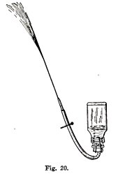
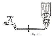
RAPID FIRE WATER GUN
GAME No. 2
Arrange the bottle as shown in Fig. 21 and fill it
half full of water. Replace the elbow by a nozzle as in Fig.
20 and your rapid fire water gun is complete. Open the clip
for an instant only for each shot.
Arrange a battle with one or more on a side, each
soldier armed with a rapid fire water gun. A man is wounded
when hit on the arm or leg and must afterwards fight without
the arm or leg; a man is killed when hit on the body or head.
The side loses which first has all of its men killed. Use
forts, trenches, tanks, etc.
EXPERIMENT No. 6
To
make and operate a pneumatic tank system of water supply.
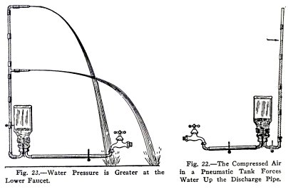
Arrange the apparatus as in Fig. 22, fill the bottle
half full of water as above, open the clip on the discharge
tube, and observe the height to which the compressed air lifts
the water.
Repeat with the apparatus as in Fig. 23. Do you
observe that the stream from the lower nozzle is longer than
that from the upper; that is, that in the pneumatic system
also the pressure is always greater at the lower faucet?
HYDRAULIC AND PNEUMATIC
ENGINEERING 17
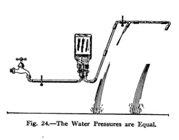
Repeat with the apparatus as
in Fig. 24. Do you observe that the streams are of the same
lengths, that is, that the pressures are equal at
faucets on the same level?
You have shown here how the compressed air in a
pneumatic tank forces water up to the faucets above; also that
the greater pressure is at the lower faucet, and that the
pressures are equal at faucets on the same level.
18 HYDRAULIC AND PNEUMATIC
ENGINEERING
 WATER AND AIR
EXPERIMENT No. 7
To
show that water is incompressible and that air is
compressible.
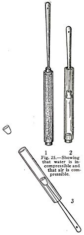
Arrange the apparatus as in Fig. 25, fill the tube
with water and try to compress it. You cannot do so because
water is nearly incompressible.
Note: Water
as slightly compressed by very great pressures; for example,
if your tube were 10 in. long and you could apply a pressure
of 3000 lbs. per square inch, the water would be compressed
1/10 inch.
Now empty out the water and try to compress the air in
the tube as in (2) Fig. 25. You will find that you can do so
quite easily because air is quite compressible.
You have demonstrated here that water is
incompressible (nearly) and that air is compressible. You know
from this that in the pneumatic tank it is the air which is
compressed and not the water.
EXPERIMENT No. 8
To
show that compressed air exerts pressure.
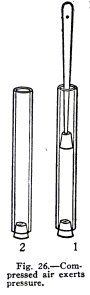
Use the apparatus shown in Fig. 26. Wet the inside of
the tube, wet the plunger and rub it on a cake of soap to make
it slippery, shove the plunger into the tube (1) and let it go
suddenly.
Do you find that the compressed air drives the plunger
out violently (2)?
Repeat with a little water above the plunger to serve
as a lubricant.
Note: When you
shove the handle into the stopper you expand the stopper
slightly. You should expand it until it fits the tube snugly
but not too tightly.
Hold the apparatus as in (3), Fig. 26 and force the
handle in until the compressed air drives out the end stopper.
You have shown here that compressed air exerts
pressure and you will understand from this how the compressed
air drives the water out of a pneumatic tank;
HYDRAULIC AND PNEUMATIC
ENGINEERING 19
also you will understand why the tank must be made of
steel, namely, to stand the pressure of the compressed air.
TRENCH GUN
GAME No. 3
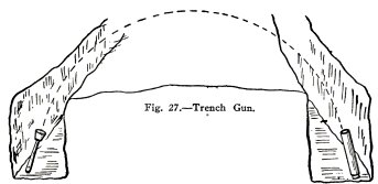
You can imitate the Stokes trench gun as follows. Put
two long strips of paper on the ground three feet apart to
represent the enemy trench. Now go back 20 or 30 feet or more,
point the tube upward and toward the enemy trench, force the
plunger in and release it suddenly. The game is to try to drop
the bomb, that is, the plunger, into the enemy trench. The
winner is the one who does it most often in a given number of
trials.
Note: Keep the
inside of the tube wet, the plunger wet and slippery with
soap, and a little water above the plunger.
HEIGHT AND DISTANCE CONTEST
GAME No. 4
Use the apparatus as above. The game is to see who can
shoot the plunger to the greatest height and to the greatest
distance.
POP GUN
GAME NO. 5
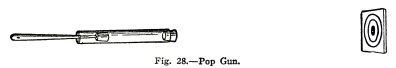
Use the apparatus as a pop gun, Fig. 28. The games
are: first, to try to hit a bull's eye, with the end stopper;
second, to see which can shoot it to the greatest distance and
the greatest height.
20 HYDRAULIC AND PNEUMATIC
ENGINEERING
THE SIPHON
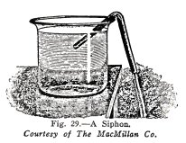
The siphon is used in many water supply systems to
make water flow over the top of a storage tank or over a hill
from a spring on one side to a house on the other, and so on.
You will first show how the siphon works, then you
will show how it is used in water supply system, and later you
will show why it works as it does.
EXPERIMENT No. 9
To make and operate a siphon.
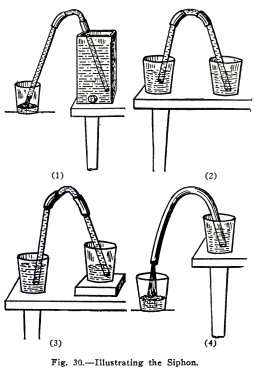
Arrange the apparatus as in (1), Fig. 30. Place one
arm of the siphon in the water and while holding the other arm
outside the tank below the water level suck the air out of the
siphon until the water runs.
Does the water run up hill to the top of the siphon
and then down hill into the tumbler?
Siphon water out of a full tumbler into an empty
tumbler and while the water is running stand them side by side
on the table, (2), Fig. 30.
Does the water stop when the level is the same in both
tumblers?
HYDRAULIC AND PNEUMATIC
ENGINEERING 21
Place one tumbler on a block of wood or a book as in
(3), Fig. 30.
Does the water flow from the upper tumbler to the
lower, and does the flow again stop when the levels are the
same?
Place the block under the other tumbler.
Are the results the same?
Repeat the above experiments with the rubber hose,
(4), Fig. 30, used as a siphon.
You have shown here: that the water runs uphill in one
arm of a siphon and downhill in the other; that it always runs
from the higher
water level to the lower; and that it stops running
when the water levels are the same.
You will show "why" the water runs, in later
experiments.
HOW THE SIPHON IS USED IN WATER SUPPLY SYSTEMS
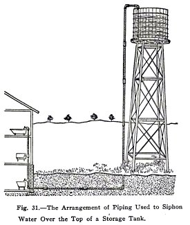
EXPERIMENT No. 10
To show how the siphon is used in water supply systems.
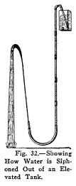
It is rather difficult to make a water-tight
connection in the bottom of a water tank and in many cases it
is not done, but instead the water is siphoned out over the
top, as shown in Fig. 31.
Illustrate this as shown in Fig, 32.
22 HYDRAULIC AND PNEUMATIC
ENGINEERING
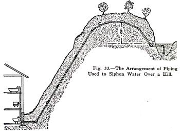
In some cases it happens that there is a good spring of water
on one side of a hill and the home in which the water is
wanted is on the other side. If the highest point of the
siphon is not more than about 25 feet (34 feet is the
theoretical limit) above the water surface in the spring, and
if the house faucets are below the level of the water in the
spring, the water can be siphoned over the hill as shown in
Fig. 33.
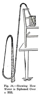
Illustrate this as shown in Fig. 34, where the back of
the chair represents the hill.
HYDRAULIC
AND PNEUMATIC ENGINEERING 23
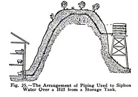
Water can be siphoned from a storage tank or reservoir
over a hill as well as from a spring and the siphon can start
at the bottom of the reservoir if this is more convenient, see
Fig. 35.
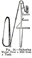
Illustrate this as shown in Fig. 36.
You have here illustrated three ways in which the
siphon is used in water supply systems. You will show later
why a siphon cannot lift water over a rise of more than about
25 feet and why the greatest theoretical lift is 34 feet.
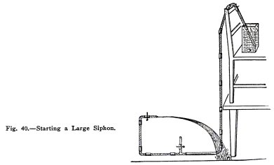
HOW TO START
A LARGE SIPHON
EXPERIMENT No. 11
To illustrate
different ways of siphon.
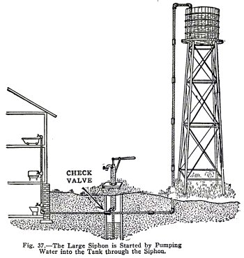
You could not start a large siphon by sucking the air
out of it with your mouth. How then are you going to start it?
You will illustrate three ways. The object in all cases is to
get the air out of the siphon and this is usually done by
filling it with water.
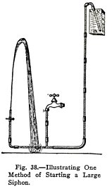
In the case illustrated in Fig. 37, the faucets are
all closed and the air is driven out of the siphon by pumping
water into the tank through the siphon. The check valve
prevents the water from running back into the pump, and when
the faucets are opened the water runs.
24 HYDRAULIC AND PNEUMATIC
ENGINEERING
This experiment is illustrated by means of the apparatus shown
in Fig. 38. The faucet here represents the pump. Start with
the tube empty except for the air in it, close the clip under
the nozzle, open the faucet until the tank is full of water,
close the faucet, and open the clip.
Does the water run through the siphon to the nozzle?
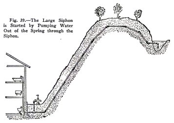
When the water is siphoned over a hill from a spring,
the siphon is usually started by connecting it to the suction
side of a pump placed on the other side of the hill in or near
the house, as shown in Fig. 39.
To start the siphon, the
house faucets are closed, the stop cock at the pump is
opened and the pump is operated until the water comes
freely; then the stop cock is closed and the water runs
whenever a faucet in the house is opened.
HYDRAULIC AND PNEUMATIC
ENGINEERING 25
This is illustrated by
arranging the apparatus as shown in Fig. 40; the tee branch
represents the pump connection and the end branch represents
the house pipe.
Close the house pipe, apply
your lips to the tee branch (to represent the working of the
pump) and suck air out of the siphon until the water flows,
then close the tee branch and open the house pipe. Does the
water flow?
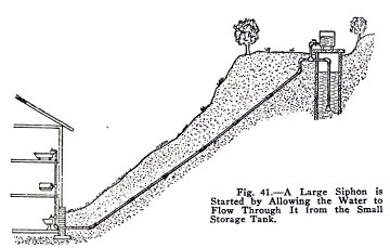
In many cases the water is
siphoned over the top of a hillside well to a house at a lower
level and the siphon is started by means of a pump near the
house as illustrated in the last experiment. Generally,
however, a small storage tank of water at the top of the
siphon is used to start it, see Fig. 41. The small storage
tank is filled by means of a pump (not shown), or by means of
a pail used to dip water from the well.
 The
Science Notebook
The
Science Notebook