26 HYDRAULIC AND PNEUMATIC
ENGINEERING
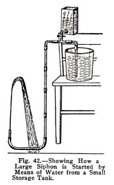
Illustrate this method of starting a large siphon with
the apparatus shown in Fig. 42. The tee at the top is
connected with the metal tank, which here represents the small
storage tank, the large pail represents the hillside well, and
the long arm of the siphon represents the pipe to the house.
Open the house faucet, then open the tee connection to
the storage tank. Does the water flow down the long arm of the
siphon? Now close the house faucet and observe that the water
runs down the short branch into the pail. Now close the tee
connection and open the house faucet. Does the siphon run?
Note: The
storage tank needs to be filled only when the siphon stops,
which may be only once or twice a year.
OTHER USES
OF THE SIPHON
EXPERIMENT No. 12
To illustrate other uses of the siphon.
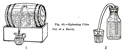
You can siphon cider, or other liquids, out of a
barrel by means of a rubber tube, (1) Fig. 43.
Illustrate this as in (2) Fig 43, where the bottle
represents the barrel and the neck of the bottle the bung
hole.
HYDRAULIC AND PNEUMATIC
ENGINEERING 27
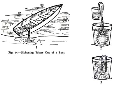
You can siphon water out of your boat when it is out
of the water, (1) Fig. 44, but not when it is afloat.
Use a tumbler to represent your boat and show that you
can siphon water out of it when it is out of the water, (2)
Fig. 44; but that you siphon water into the boat if it is
afloat, (3) Fig. 44, because the water outside the boat is
higher than that inside.
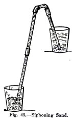
You can siphon sand, gravel, and mud with the water
when necessary. Illustrate this by siphoning sand or mud with
the water from one tumbler to another, Fig. 45.
28 HYDRAULIC AND
PNEUMATIC ENGINEERING
VELOCITY OF
FLOW
EXPERIMENT No. 13
To show that
the velocity of the water in a siphon is greater, the
greater the distance,
between the water levels about the two arms.
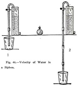
Arrange the siphon with a small difference in water
level as shown in (1) Fig. 46 and allow the water to run for
15 seconds; then arrange it with a greater difference as in
(2) Fig. 46 and again allow the water to run for 15 seconds.
Does more water flow in (2) than in (1), that is, is
the velocity greater the greater the difference in water
level?
OTHER
SIPHONS
EXPERIMENT No. 14
To make and operate a
double siphon and a three legged siphon.
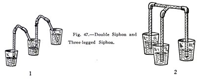
Start a double siphon, (1) Fig. 47. Raise the tumblers
one at a time, then two at a time.
Does the water always flow from the upper tumbler or
tumblers to the lower and does it always stop flowing when the
water levels are the same?
Start a three legged siphon, (2) Fig. 47 and repeat
the above experiments. Are the results the same?
HYDRAULIC AND PNEUMATIC
ENGINEERING 29
HOW TO START
A SMALL SIPHON
EXPERIMENT No. 15
To illustrate two ways of starting a small siphon.
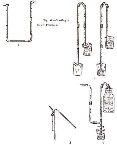
You have been starting your small siphon by sucking
air out of the long arm. You can also start it as shown in (1)
Fig. 48. Fill the siphon with water to force the air out,
close the ends with your fingers, invert the siphon, and when
the upper end is under water in the upper tumbler remove both
fingers, (2) Fig. 48.
Glass siphons used to siphon acid have a starting tube
on the outside arm, (3) Fig. 48.
Illustrate the use of this by siphoning water out of a
bottle with the siphon shown in (4) Fig. 48. Place the upper
end in the water, close the lower end, suck out a little air,
and open the lower end.
Practice until you can start the siphon without
getting water (representing the acid) on your fingers or lips.
30 HYDRAULIC AND
PNEUMATIC ENGINEERING
AN ENCLOSED
FOUNTAIN
EXPERIMENT No. 16
To make and operate an enclosed fountain.
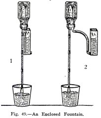
Arrange the apparatus as shown in (1) Fig. 49; this is
really a siphon with a bottle at the top. Start with 2 inches
of water in the bottle, insert the stopper with tubes, invert
the whole apparatus, and put the short arm in the tank
filled with water.
Does the water run and is there a fountain in the
bottle?
Arrange the apparatus as in (2) Fig. 49, lift the tank
until there is about 2 inches of water in the bottle, then
arrange as shown.
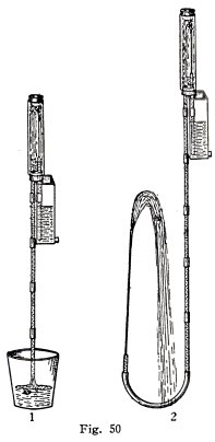
Is there a fountain in the bottle? Repeat both of
these experiments but use instead of the bottle, a wide glass
tube closed at the top with a solid rubber stopper, (1) Fig.
50.
Make two fountains as shown in (2) Fig. 50, one
enclosed and one in the open.
HYDRAULIC AND PNEUMATIC
ENGINEERING 31
ATMOSPHERIC PRESSURE
You have made a number of experiments with siphons and
you have learned how they act under different circumstances;
you will now make some experiments which will help you to
understand "why" they act as they do.
Water moves through a siphon because it is forced to
do so by atmospheric pressure. You will first make a number of
experiments to show that the atmosphere exerts pressure and
then you will show how and why this atmospheric pressure
forces water through a siphon.
AIR HAS WEIGHT
If you were asked the question "How much does air
weigh?", you would probably answer off hand, "Air has no
weight at all." Air, however, has considerable weight and it
would take a very strong man indeed to carry a weight equal to
that of the air in a house of medium size.
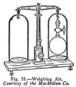
You cannot weigh air with the apparatus you have at
hand but this is how it is done. The apparatus used is
illustrated in part in Fig. 51. The air is pumped out of
the flask, by means of an air pump (not shown). The flask is
then balanced exactly on the fine scales and air is admitted
to the flask again. It is found that the flask weighs more
when it is filled with air than when it is empty, and this
proves that air has weight.
A cubic foot of air, at the surface of the earth and
at ordinary temperatures is found in this way to weigh about 1
1/4 oz. This is not a great weight, but when you come to
calculate the weight of air in a house of medium size you find
that it amounts to a very great deal, for example, make the
following calculation:
A house with a flat roof is 40 feet long, by 30 feet
wide, by 24 feet high; find the weight of air in it,
neglecting the space occupied by partitions, furniture, etc.
32
HYDRAULIC AND PNEUMATIC ENGINEERING
The house contains 40 x 30 x 24 28,800 cubic feet of
air, and since each cubic foot of air weighs 1 1/4 ozs. the
house contains 28,800 x 1 1/4 = 36,000 oz. of air, and since
there are 16 ozs. in 1 lb.
36000
the house contains --------
= 2250 lbs. of air.
16
The house contains 2250 lbs. of air or over a ton of
air (1 ton = 2000 lbs). This is a very astonishing fact,
especially to those of us
who have never thought of air as having any weight at
all.
AIR EXERTS PRESSURE
You have learned from your lessons in Physical
Geography at school that we live at the bottom of an ocean of
air the atmosphere which is many miles deep; and when you
remember that a cubic foot of air weighs 1 1/4 ozs. - you are
in a position to see that the atmosphere must exert great
pressure on everything at the earth's surface.
It has been found by repeated experiments that the
atmosphere exerts a pressure of 14.7 lbs. (nearly 15 lbs.) on
each square inch of everything at the earth's surface. This
means, for example, that on every square inch of our bodies
the atmosphere exerts a pressure of 14.7 lbs. We might think
that this would crush our bodies, until we remember that
everything inside our bodies exerts the same pressure outward,
our blood, the air in our lungs, etc.
A pressure of 14.7 lbs per square inch is equal to the
pressure at a depth of 34 feet under water, that is, if the
air could be removed from the earth and be replaced by water,
it would require a depth of 34 feet of water all over the
earth to produce a pressure equal to that produced by the
atmosphere, namely, 14.7 lbs. per square inch.
You will now make experiments to show that the
atmosphere exerts pressure
EXPERIMENT No. 17
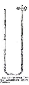
To show that the atmosphere exerts pressure.
Make a U tube, Fig. 52, run water through the tube
until all the air bubbles are gone, then empty out part of the
water until the U
HYDRAULIC
AND PNEUMATIC ENGINEERING 33
is a little more than half full. The water in the two
arms is then at the same level.
Now apply your lips to the coupling on one arm, suck
out the air, and close the clip. Do you observe that, when you
suck out the air, the water in the open arm descends while
that in the other arm rises?
The explanation is as follows. Everything on the earth
is at the bottom of an ocean of air many miles deep, and since
this air has weight it exerts pressure on everything on the
earth. Now when both arms of the U tube are open, the water
level is the same in both and the pressure of the air on the
water surface in each is the same, namely, the pressure of the
atmosphere. When you remove the air from the closed side,
however, you remove the pressure of the atmosphere from this
side and the pressure of the atmosphere in the open side
forces the water down on the open side and up the closed side.
This experiment shows you that the atmosphere exerts pressure.
Repeat and make experiments of your own.
EXPERIMENT No. 18
To show that the atmosphere will support a column of
water.
Arrange the apparatus as in (1) Fig. 53, fill the tube
with water, close one end with a clip and hold both ends in
the position illustrated. Does the water remain in the tube?
It remains because the pressure of the atmosphere downward on
the water in the open tube supports the column of water in the
long tube.
Turn the open end sidewise and then downward. Does the
water remain in the tube? It remains because the atmosphere
exerts pressure sidewise and upward and supports the water.
34 HYDRAULIC AND PNEUMATIC
ENGINEERING
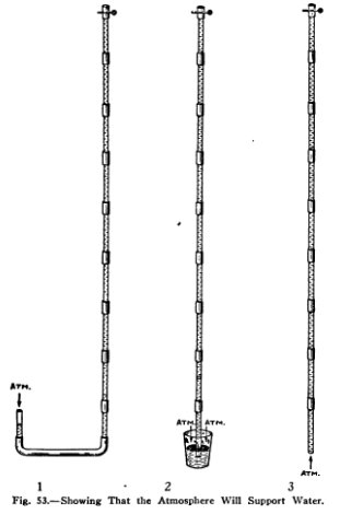
Arrange the apparatus as shown in (2) Fig. 53. Place
the lower end of the tube in a tumbler of water, stand on a
chair, and suck the air out of the tube, then close the upper
end.
Does the water remain? It remains because the pressure
of the atmosphere downward on the water in the tumbler
supports the water
in the tube.
HYDRAULIC AND PNEUMATIC
ENGINEERING 35
Lift the tube out of the tumbler, (3) Fig. 53, and the
water will remain in the tube because it is supported by the
upward pressure of the atmosphere. This is possible only with
very narrow tubes. The tube you have used in these experiments
is about 6 feet long and you have shown that the atmosphere
will support a column of water 6 feet high. If you had a tube
of sufficient length you could show that the atmosphere will
support a column of water 34 feet high, but no more.
36 HYDRAULIC AND
PNEUMATIC ENGINEERING
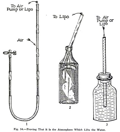
EXPERIMENT No. 19
To prove that it is the pressure of the atmosphere which lifts
the water.
Make a U tube (1) Fig. 54, with four tubes on one side
and two on the other, fill it half full of water so that the
two tubes on the short side are quite full, then close the top
of this side with a coupling and clip. Now suck the air out of
the long side. Do you observe that the water does not move?
It does not move because although you have decreased
the air pressure in the long side, the atmosphere cannot get
at the water in the short side to force it down.
Open the top and repeat the experiment. Does the water
move?
To show this in another way. Fill a bottle (2) with
water, place a glass tube in it and suck the air out of the
tube. You observe that when you remove the air pressure from
the water in the tube, the atmospheric pressure on the water
in the bottle forces the water up into your mouth.
Now fill the bottle quite full to exclude the air, and
close it with a one hole rubber stopper which has one glass
tube stuck in the under side and another in the upper side,
(3). Suck the air out of the upper tube. Do you find that the
water does not rise?
It does not rise because although you have decreased
the air pressure in the upper tube, the atmosphere cannot get
at the water in the bottle to force it into
your mouth.
You have proved here that it is the pressure of the
atmosphere which lifts the water.
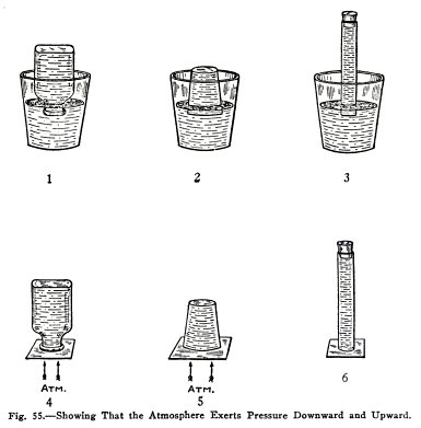
EXPERIMENT No. 20
To show in other ways that the atmosphere exerts
pressure downward and upward.
Fill the bottle with water, close the top with the
hand, invert the bottle in a pail of water, and remove the
hand under water, (1) Fig. 55.
The downward pressure of the atmosphere on the water
surface in the pail supports the water in the bottle.
Repeat with the tumbler and tube as shown in (2) and
(3).
Fill the bottle with water, cover with a piece of
paper, hold the paper on with the hand, invert the bottle and
remove the hand, (4).
The paper is held on by the upward pressure of the
atmosphere.
Repeat this experiment with a tumbler and tube, (5)
and (6).
HYDRAULIC AND
PNEUMATIC ENGINEERING 37
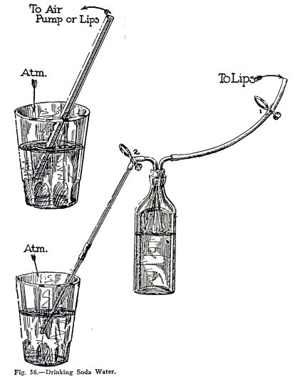
EXPERIMENT No. 21
To illustrate two simple uses of atmospheric pressure.
DRINKING SODA WATER
When you drink soda water through a straw or glass
tube, (1) Fig. 56, you simply produce a vacuum in your mouth
and it is the atmosphere which forces the soda water into your
mouth.
Illustrate this with the apparatus, (2) Fig. 56 in
which the bottle represents your mouth. Suck air out of the
bottle, close clip 1, and open clip 2.
Does the atmosphere force water into the bottle? It
forces soda water into your mouth in the same way.
38 HYDRAULIC AND PNEUMATIC
ENGINEERING
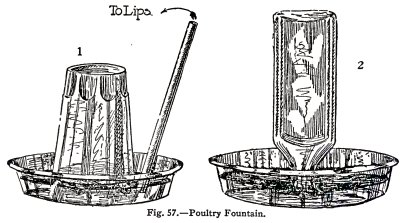
POULTRY DRINKING FOUNTAINS
Fill a tumbler with water, place two pieces of
lead pencil across the top, cover with a saucer, and
invert tumbler and saucer, (1) Fig. 57.
Repeat with the glass bottle, (2).
Does the water run out only until the edge of the
tumbler or bottle is covered?
To imitate the poultry drinking the water, suck water
out of the saucer by means of a glass tube until the water is
below the edge of the tumbler.
Does air enter and water run out only until the edge
is again covered?
The atmosphere supports the water.
Note: The
atmosphere could support the water in a fountain 34 feet high
but no higher.
HYDRAULIC AND PNEUMATIC
ENGINEERING 39
THE SIPHON (Continued)
THE "WHY" OF THE
SIPHON
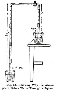
The reason "why" water flows through a siphon is as follows:
Suppose, for example, you have a siphon, Fig. 58, closed at
the top with a clip. The atmospheric pressure on the water in
the right hand tumbler supports only 1 foot of water, while in
the left hand tumbler it supports two feet of water.
Now the atmospheric pressure on each is equal to the
pressure of a column of water 34 feet high, therefore at the
top of the siphon the pressure at the right of the clip
is
34 - 1= 33 feet of water;
at the left of the clip is
34 - 2 = 32 feet of water.
The pressure at the right is greater than that at the
left and if the clip is opened the water flows from right to
left, that is, from the upper tumbler to the lower tumbler.
This is the "why" of the siphon.
40 HYDRAULIC AND
PNEUMATIC ENGINEERING
PUMPS
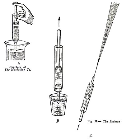
EXPERIMENT No. 22
To illustrate the action of a syringe.
The simplest kind of pump is the syringe, (A) Fig. 59.
When you lift the plunger, there is a vacant space or partial
vacuum left below
the plunger and the
atmospheric pressure on the water in the tumbler lifts water
into the syringe.
Illustrate this by means of the syringe,
(B)
Fig. 59. Soap the plunger to make it slippery, fill the
syringe, lift the nozzle end and squirt the water out,
(C) Fig. 59.
HYDRAULIC AND PNEUMATIC
ENGINEERING 41
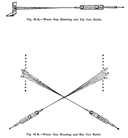
WATER GUN SHOOTING
GAME No. 6
The syringe makes a fine water gun. Use it as follows
:
(1) Put up a bent piece of cardboard as a target and
try to hit it from various distances, (A) Fig. 60.
(2) See who can send the stream to the greatest
height.
(3) See who can send the stream to the greatest
distance.
BIG GUN BATTLE
GAME No. 7
Each player here puts up the same number of lead or
paper soldiers and at a given signal each starts to knock down
the enemy soldiers with his water gun which here represents a
large caliber gun firing shells, (B), Fig. 60.
The winner is the one who first knocks down all the
enemy soldiers.
42 HYDRAULIC AND PNEUMATIC ENGINEERING
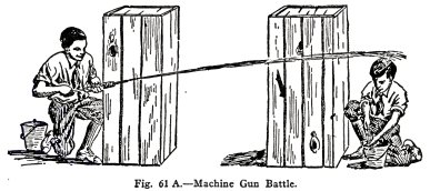
MACHINE GUN BATTLE
GAME No. 8
Each player is behind a barricade which represents a trench
(A), Fig. 61 and is armed with a syringe which here represents
a machine
gun. The rules about wounded and
killed are the same as in Game No. 2. The winning side is the
one which first kills all the enemy.
THE DIABLO WHISTLE
GAME No. 9
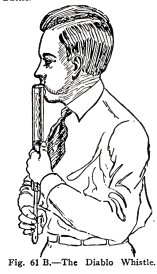
The apparatus, Fig. 61 B makes a most uncanny whistle
when you blow into it as illustrated and move the plunger up
and down.
The game is: (1) to make the most diabolical sound you
can; (2) to play the eight notes of an octave as well as you
can; (3) to play a tune if you can.
HYDRAULIC AND PNEUMATIC
ENGINEERING 43
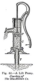
THE LIFT PUMP
Common pumps are of two kinds: lift pumps, Figs. 62,
63, which lift water only to the spout; and force pumps, Fig.
65, which force the water to any height above the spout. Both
types of pumps have two valves which open upward.
The Lift Pump, Fig. 62, has one valve S at the bottom
of the barrel C and another V in the plunger P. The
atmospheric pressure lifts water from the well into the pump
through the suction pipe T.
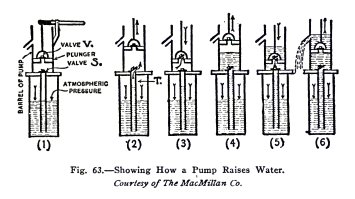
The way the lift pump lifts water is illustrated in
drawings 1 to 6, Fig. 63.
Before the pump is started the condition is that shown
in (1): both valves are closed and the water level in the
suction pipe is the same as that in the well.
When the plunger is raised as in (2), the air in the
barrel beneath the plunger is given more room, it expands and
its pressure on the valve S is decreased; the air in the
suction pipe then lifts the valve S and part
44 HYDRAULIC AND PNEUMATIC
ENGINEERING
of it expands into the barrel; this decreases the air
pressure on the water in the suction pipe, and the atmospheric
pressure on the water in the well forces some water into the
suction pipe.
When the plunger is shoved down as in (3), valve S
closes and the air in the barrel is forced up through the
plunger valve V.
When the plunger is raised again as in (4), the
operations explained in (2) take place again, and the
atmospheric pressure on the water in the well forces more
water into the suction pipe and also into the barrel.
When the plunger is shoved down again as in (5), valve
S closes again and all the air in the barrel, with part of the
water, is forced up through the plunger valve V.
When the plunger is raised again as in (6), the water
above the plunger is lifted to the spout and the atmospheric
pressure on the water in the well forces more water into the
suction pipe and barrel.
After this (5) and (6) are repeated as long as the
plunger is operated.
EXPERIMENT No. 23
To make and operate a Lift Pump.
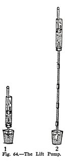
Arrange the apparatus as shown in (1) Fig. 64. Soap
the plunger, place the lower end of the narrow tube in a glass
of water, and move the plunger up and down slowly.
Do you find that: on the up stroke of the plunger,
water moves up through the narrow tube and lower valve into
the pump barrel; and on the down stroke, the water remains at
the same height because the lower valve closes, but as the
plunger moves down, the air and water pass through the plunger
valve? Do you notice that on the succeeding up strokes, water
rises and flows over the top, and on succeeding down strokes
it moves through the plunger valve?
HYDRAULIC AND PNEUMATIC
ENGINEERING 45
Attach three or four narrow tubes below the pump
barrel to make the suction pipe longer, (2) Fig. 64, and
repeat the experiment.
Attach all the narrow tubes and the rubber tube to the
pump barrel and repeat the experiment.
Do you find that the atmospheric pressure on the water
in the tumbler lifts the water into the pump barrel when you
move the plunger up?
The pressure of the atmosphere is equal to the
pressure of a column of water 34 feet high and no more,
therefore, a pump must be placed at a less height than 34 feet
above the water it is pumping and in practice the height is
usually 25 feet or less.
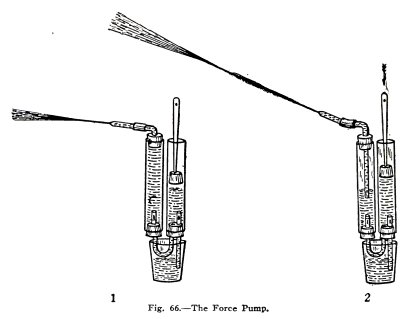
THE FORCE PUMP
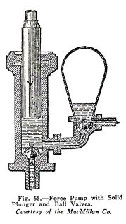
The force pump, Fig. 65, has a valve A at the bottom of the
barrel, but the plunger V is solid, the discharge pipe leaves
the barrel below the plunger, and the second valve B is below
an air chamber at one side; also the top of the barrel is
closed by an inverted U shaped leather ring which surrounds
the plunger and prevents the water from escaping.
It pumps water in exactly the same way as does the
lift pump.
The ball valves shown here have the advantage that
they wear evenly because they turn continuously. Both lift
pumps and force pumps can have either ball valves or common
flap valves.
The air chamber protects the force pump from excessive
strain because the air compresses under excessive pressure; it
also tends to keep a steady stream in the discharge pipe
because the compressed air continues to force the water out of
the air chamber while the plunger is making the up stroke.
46 HYDRAULIC AND
PNEUMATIC ENGINEERING
EXPERIMENT No. 24
To make and operate a Force Pump.
Arrange the apparatus as shown in (1), Fig. 66. Soap the
plunger, place the suction pipe in a tumbler of water, pour a
little water above the plunger to make sure it is air tight;
and move the plunger up and down.
Do you observe that on the up stroke water enters the
barrel through the valve, and that on the down stroke it is
forced into the side tube through its valve? If the valves are
not quite air tight pour water into both tubes to cover them.
Make an air chamber in the side tube by inserting a
short narrow glass tube below the upper stopper, (2), Fig. 66.
Operate the force pump.
Do you observe that the air is slightly compressed in
this chamber, on the down stroke of the plunger, and that this
compressed air keeps the water flowing for a short time after
the stroke is finished.
HYDRAULIC AND PNEUMATIC
ENGINEERING 47
Repeat the experiment using short quick strokes of the
plunger.
Do you find that you can keep a fairly steady stream
issuing from the nozzle?
Water can be forced to any height in the discharge
pipe of a force pump but the suction lift should not be more
than about 25 feet, that is the pump plunger must be within 25
feet vertically of the water it is pumping.
EXPERIMENT NO 25
To show how water is pumped into an elevated tank.
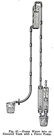
A lift pump can be used to pump water into an elevated
tank only if the top of the tank is not over 25 feet (34 feet
theoretically) above the water in the well. If the tank is
higher than this, a force pump must be used.
Illustrate this use of a force pump by means of the
apparatus shown in Fig. 67. Pump water into the tank and then
draw off some through the faucet below. This equipment
represents a complete water supply system.
FORCE PUMP CONTEST
GAME No. 10
The game here is to see who can force the water to the
greatest height and to the greatest distance. Tie the stoppers
in with cord and stretched rubber bands. Use the apparatus
shown in (2) Fig. 66.
48 HYDRAULIC AND
PNEUMATIC ENGINEERING
HYDRAULIC APPLIANCES
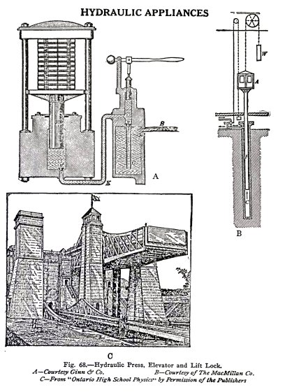
The hydraulic press (A),
hydraulic elevator (B). and hydraulic lift lock (C), Fig. 68,
are each operated by means of pressure exerted on water, and
in order to understand them you will first illustrate Pascal's
law which tells how pressure is transmitted by water.
HYDRAULIC AND PNEUMATIC
ENGINEERING 49
PASCAL'S LAW
Pascal's Law is: Pressure exerted on a liquid is
transmitted equally and undiminished in all directions.
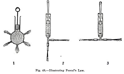
This law is usually illustrated by means of the
apparatus shown in (1) Fig. 69. It is a syringe with a glass
bulb which has five nozzles of the same size and in the same
plane. When the syringe, filled with water, is held with the
nozzles horizontal and the plunger is forced in, the streams
which issue from the nozzles are of exactly the same length.
This shows that pressure exerted on water is transmitted
equally in all directions. This is very surprising because
since the plunger exerts the pressure in the direction of the
front stream we might expect this stream to be the longest: we
find, however, that they all have the same length.
EXPERIMENT
No.
26
To show that pressure on water is transmitted equally in all
directions.
Use the apparatus (2) Fig. 69. Fill the tube with
water, insert the plunger, hold the nozzles horizontal, and
force the plunger in steadily.
Are the streams of equal length?
50 HYDRAULIC AND PNEUMATIC
ENGINEERING
Repeat with the apparatus (3)
Fig. 69.
With (2) Fig. 69 you show that the pressure is
transmitted equally forward and sidewise, and with (3) Fig.
69, that it is transmitted equally in both sidewise
directions.
This experiment shows that water transmits pressure
equally in all directions. The experiments described below
show that it transmits it equally and undiminished in all
directions.
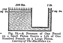
The two cylinders and
connecting pipe, Fig. 70, are filled with water and each
cylinder is fitted in with a water tight piston ; the
area of cross section of the small piston is 1 sq. in. and of
the large piston, 100 sq. in. If now a pressure of 1 Ib is
exerted on the small piston, it is found that this
pressure is transmitted equally and undiminished by the water,
and that therefore, the upward pressure on the large piston is
1 lb. on each sq. in. or the total pressure upward is 100 lbs.
That is, 1 lb. on the small piston supports 100 lbs. on the
large piston.
This is very surprising and it looks as if we were
getting something for nothing. This is not so, however,
because if the small piston is moved down 1 inch, the large
piston moves up only 1/100 of an inch. That is, "what is
gained in force is lost in distance moved."
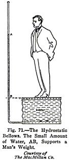
The hydrostatic bellows, Fig.
71, is an apparatus of this kind and it illustrates Pascal's
law beautifully. It consists of two disks of wood connected by
a water-proof canvas cylinder to make a collapsible drum. A
small pipe passes through the
lower disk and opens into the drum.
If now the drum is filled with water and a man stands
on the upper disk, it is found that a very small amount
of water, AB, in the pipe will support his weight.
 The
Science Notebook
The
Science Notebook