HYDRAULIC AND PNEUMATIC ENGINEERING 51
This is very striking and it is explained as above.
If, for example, the area of the pipe is 1 sq. in. and that of
the disk is 500 sq. in. then 1 ft), of water in AB will
support a weight of 500 lbs. on the disk. Similarly 1/2 lb. of
water in AB will support 1/2 x 500 = 250 lbs. on the disk, or
1/4 lbs. of water in AB will support 1/4 x 500 = 125 lbs. on
the disk, and so on.
EXPERIMENT No. 27
To make and operate a hydrostatic bellows.
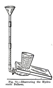
Arrange the apparatus as shown in Fig. 72. Place the
book on the empty observation balloon, and fill the balloon
with water until it is about half full. Do you
observe that a very little water in the tube supports the
weight of one end of the book.
Place an empty tumbler on the book and fill it with
water. Do you find that a small extra amount of water in the
tube supports the glass of water?
Remove the tumbler and press down on the book with
your hand. Do you find that to lift water in the tube you must
exert a force much greater than the weight of this water.
These experiments are certainly very striking and they
illustrate Pascal's law as follows: The weight of the extra
water in the tube exerts pressure downward on an area equal to
that of the inside of the tube; this pressure is transmitted
equally and undiminished in all directions by the water, and
is exerted against each equal area of the inside
52 HYDRAULIC AND
PNEUMATIC ENGINEERING
THE HYDRAULIC PRESS
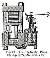
The hydraulic press is an application of Pascal's law
and of the hydrostatic bellows. It is used where great
pressure is required, for example, to compress merchandise, to
bend ship plates, to lift great weights, and so on.
The press has a force pump with handle P which
operates the small piston A in the small cylinder C and pumps
water from the reservoir L through the valve d, through the
connecting pipe and valve v, and into the large cylinder D.
The large piston B, or ram as it is called, moves up and down
in D. Both A and B have collars which prevent the escape of
water.
If now the end of ram B has an area 100 times as great
as the end of A, then each 1 lb. exerted on A exerts a lift of
100 lbs. on B, and so on.
EXPERIMENT
No.
28
To make and operate a
hydraulic press.
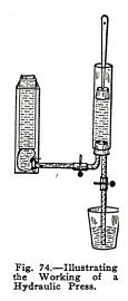
Arrange the apparatus as shown in Fig. 74, where the
tin can in the tank represents the ram and where the balloon
represents the collar of the ram. Soap the plunger to make it
slippery.
Open lower clip, raise the plunger, close lower clip,
open side clip and lower the plunger. Repeat until the balloon
is partly filled with water.
Now fill the tin can with water and repeat the
operations above.
Do you find that a small force on the plunger will
lift the relatively large weight of the tin can full of water?
You have shown here that on the hydraulic press a
small force moving the small piston a long distance lifts a
great weight on the large piston a small distance.
HYDRAULIC AND PNEUMATIC ENGINEERING 53
THE HYDRAULIC ELEVATOR
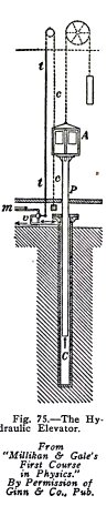
The simplest form of hydraulic elevator is illustrated
in Fig. 75. The passenger cage A is securely fastened to the
top of a long ram P which moves up and down in a deep cylinder
C. The elevator is raised by the city water pressure or, if
this pressure is not sufficient, by the pressure of water
pumped into a tank on the roof of the building. The water
enters through the pipe m and through the three-way valve if,
and it leaves through the three-way valve and the lower pipe.
The weight of the cage and ram is partly
counter-balanced by the weight shown. When water is admitted
to the cylinder, it exerts pressure upward on the bottom of
the ram and raises the ram and cage; when the discharge pipe
of the cylinder is opened, the cage and ram descend by their
own weight and drive the water out of the cylinder.
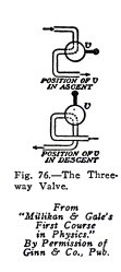
The operation of the three-way valve is illustrated in
Fig. 76. The lever handle is weighted at the end and is
operated by the cord t, t, c, c, which passes through the
cage. When the operator pulls the cord up the valve takes the
upper position, water is admitted to the cylinder, and the ram
and cage are raised. When the operator pulls the cord
down, the valve takes the lower position and connects
the cylinder with the discharge pipe;
From the cage and ram then descend by their own weight
and in doing so force water from the cylinder to
the
sewer.
54 HYDRAULIC AND PNEUMATIC
ENGINEERING
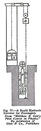
When speed is desired, for example in carrying passengers, the
elevator is arranged as shown in Fig. 77. The plunger or ram P
moves in a cylinder C. Both ram and cylinder carry a number of
large separate pulleys, side by side, around which a steel
cable is passed a number of times and then attached to the
counterpoise weight D.
If, for example, the steel cable makes 10 loops around
the pulleys there are 20 strands between the two sets of
pulleys. If then the ram moves 1 foot each strand is
lengthened 1 foot and the counterpoise is pulled down 20 feet.
Since the cable attached to the passenger cage passes around
the pulley of the counterpoise as shown, each foot the
counterpoise descends raises the cage 2 feet. Thus if the ram
moves 1 foot, the counterpoise moves 20 feet and the cage, 40
feet. This gives the passenger cage a speed forty times that
of the ram.
The ram is moved by water from the city mains which is
controlled by a three-way valve as described above.
HYDRAULIC AND PNEUMATIC ENGINEERING 55
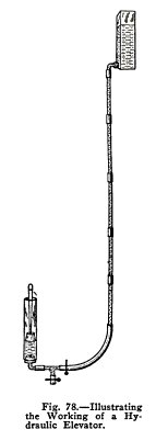
EXPERIMENT No. 29
To make and operate a hydraulic elevator.
Arrange the apparatus as shown in Fig. 78. Soap the
plunger well to make it slippery.
Open side clip. Is the cage raised? Close side clip.
Does it stop?
Open lower clip and press down gently on the cage.
Does it descend? Close lower clip. Does it stop?
Now open and close side clip to raise the cage a short
distance at a time. Do you find that you control the elevator
perfectly as it rises?
Now open and close lower clip while you force the cage
down a short distance at a time. Do you find that you can
control the elevator perfectly as it descends and that you
cannot move it down when the clip is closed?
You have shown here how the ram and cage of an
elevator are raised by water pressure and how they descend by
their own weight. You have shown also that you can stop them
anywhere, while rising or descending, by closing the proper
valve.
HYDRAULIC LIFT LOCKS
CANAL LOCKS
56 HYDRAULIC AND PNEUMATIC
ENGINEERING
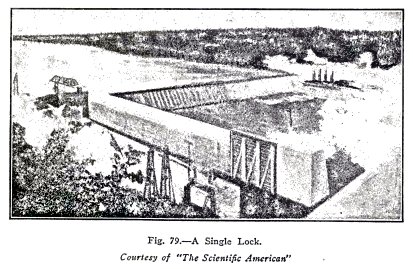
An ordinary canal lock, Fig. 79, is used to raise or
lower steamers a few feet to enable them to pass up or down
stream, around a rapid, dam or waterfall. It is simply a short
canal with a pair of gates at each end.
If the steamer is going up stream, it sails through
the lower gates of the lock; the lower gates are closed behind
it; water is admitted to the lock until its
level is equal to that of the water above the lock; the upper
gates are then opened, and the steamer sails out of the lock
at the upper level. If the steamer is going down stream the
reverse operation takes place.
If the difference in level is considerable but over
some distance, a number of these locks are used, for example,
if the difference in level were 80 feet in a distance of two
miles, there might be, in the two miles, 4 locks with a
difference of level of 20 feet each or 8 locks with a
difference of 10 feet each, and so on.
When the difference in level is great in a short
distance, however, a lift lock must be used.
LIFT LOCKS
Lift locks are so called because the whole lock, with
the water in it and the ship, is lifted vertically from the
low level to the high, or is lowered vertically from the high
level to the low. They are always in pairs and the weight of
one balances the weight of the other.
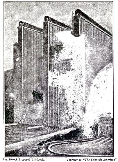
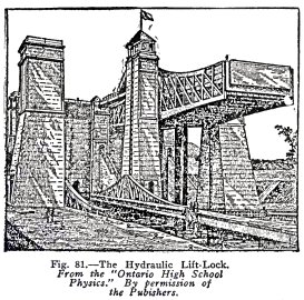
The lift lock shown in Fig. 80, is one that it is
proposed to build on a canal between Lake Erie and Lake
Ontario. It will take ships 650 feet long and of 30 foot
draft, and will lift or lower them through a vertical height
of 208 feet. The inner side of one will be connected with the
inner side of the other by 56 steel cables which pass over 56
sheaves of 20 foot diameter. The outer side of each will be
connected with large concrete counterweights by means of steel
cables passing over 56 sheaves on each side. The locks will be
raised and lowered by means of electrical power applied to the
rims of each sheave. The gates at the ends of each lock and at
the ends of the upper and lower canal will be opened and
closed by being moved down and up vertically. The diagram
shows how the locks will look when one ship is being raised
and another lowered. The building at the right is a plant in
which electrical power will be developed from the excess water
from the upper canal. A small part only of this power will be
used to operate the locks.
HYDRAULIC AND PNEUMATIC
ENGINEERING 57
58 HYDRAULIC AND
PNEUMATIC ENGINEERING
HYDRAULIC LIFT LOCKS
Hydraulic lift locks are so called because they are
operated by means of water. Each lock is a large steel tank
securely attached to the top of a very large ram which moves
up and down in a deep cylinder. The two cylinders are
connected by a pipe through which the water flows from one to
the other, the flow being controlled, or stopped entirely, by
means of a valve.
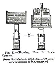
The operation of the locks will be understood from
Fig. 82. If the steamer is going up stream: it sails into the
lock B which is down and the lock gate is closed; a little
water is admitted to the lock A which is up, to make it weigh
more than the lower lock B and the steamer; the valve R is
opened; the upper lock descends and its ram P
1 forces
water from its cylinder into that of the lower lock; the
pressure of this water raises the ram P
2 , the
lower lock and the steamer, to the upper level; the gates
are opened; and the steamer sails out at the upper level.
HYDRAULIC AND PNEUMATIC
ENGINEERING 59
If the steamer is going down stream; it sails into the
upper lock and the gates are closed; water is admitted to the
upper lock to make it weigh more than the lower lock; the
valve R is opened; water is forced from the cylinder of the
upper lock to that of the lower as the upper lock descends and
the lower lock rises; the gates are opened; and the steamer
sails out at the lower level.
Note. You
might think that the presence of the steamer in one lock would
make it weigh more than the other lock, but you will learn in
Experiment 36 that a ship displaces its own weight of water
and that therefore the one lock, plus water, plus steamer,
weighs the same as the other lock plus water.
EXPERIMENT No. 30
To make and operate a
hydraulic lift lock.
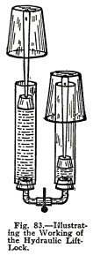
Use the apparatus shown in Fig. 83. The wide tubes and
plungers represent the cylinders and rams of a real lift lock,
and the clip represents the control valve. The inverted
tumblers represent the locks, they should of course be right
side up but you have no way of fastening them.
Place a button or pebble on the lower lock to
represent a ship, open the clip and press down on the upper
lock. Is the ship raised?
Lower a steamer in the same way.
Now place a steamer in the lower lock and press down
on the upper lock while you open and close the clip from time
to time. Do you find that the plungers stop as soon as you
close the clip?
This shows how the rams of a real lift lock can be
stopped anywhere by closing the valve R, Fig. 82. Water is
incompressible, as you know from Experiment, No. 7, and when
valve R is closed the rams cannot move because the water in
the cylinders cannot be compressed and cannot move.
Repeat this but close the clip only partly.
Do you find that the plungers can move slowly and
that you can regulate the speed by opening of the clip more or
less?
60 HYDRAULIC AND
PNEUMATIC ENGINEERING
This shows how the rams in a real lift lock can be
allowed to move rapidly or slowly by opening the valve R more
or less
In this experiment you have illustrated the working of
a hydraulic lift lock: you have shown that the downward
movement of one ram drives water into the second cylinder and
that the pressure of this water raises the ram in the second
cylinder; you have shown also that the rams can be stopped
anywhere by closing the valve R or that they can be made to
move very slowly by closing the valve partly.
THE PRESSURE EXERTED BY WATER
HYDRAULIC AND PNEUMATIC
ENGINEERING 61
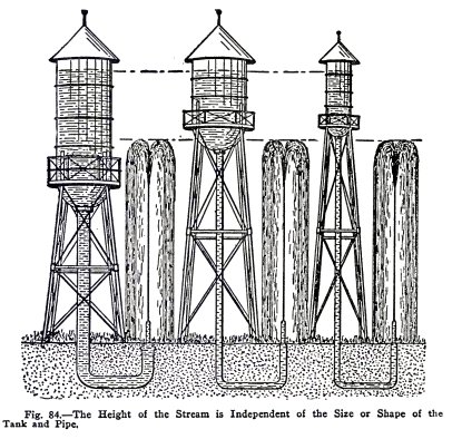
A very astonishing fact is illustrated in Fig. 84,
namely that the pressure at the nozzles is the same no matter
what size and shape the tank may be and no matter what size
and shape the pipe may be, provided the water level in the
tank is at the same distance above the nozzle in all cases.
You will now prove this.
EXPERIMENT No. 31
To show that the pressure at a nozzle is independent of the
size and shape of the tank and pipe.
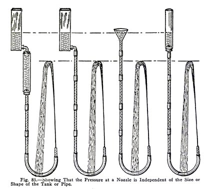
Make the experiments illustrated in Fig. 85 one after
the other using the same nozzle in all. Are the streams of the
same height in all cases if the water level in the tank is at
the same distance above the nozzle?
62 HYDRAULIC AND PNEUMATIC
ENGINEERING
You have shown here that the pressure exerted by water
is independent of the volume of the water but that it depends
upon the height of the water above the nozzle. This is known
as the Hydrostatic Paradox which you will now illustrate.
THE HYDROSTATIC PARADOX
The Hydrostatic Paradox is stated as follows : The
pressure exerted by a liquid on any base is
independent of the volume of the
liquid, but depends only on the area of the base, the
depth of the liquid, and the
density
of the liquid.
Note. The
density of a liquid is its
weight per cubic foot, or per cubic inch, or per cubic
centimeter.
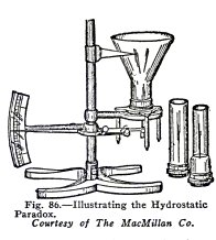
The hydrostatic paradox is illustrated by means of the
apparatus shown in Fig. 86. The three tops are of different
sizes and shapes, but they fit a common base. The bottom of
this base is covered by a sheet of rubber or by a sheet of
corrugated metal. The base sinks as the pressure increases and
moves the pointer, which indicates the pressure.
If the tops are screwed to the base, one after the
other, and then filled with water to the same
height, the pointer
indicates the s
ame pressure
in all cases.
The volume of water in the tops is different in each
case, but the pressure is the same in all. This shows that the
pressure exerted by a liquid is
independent of the volume of the liquid,
provided the
area of the base, the
depth and the
density of the liquid are
the same in all cases.
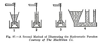
Another form of this apparatus is shown in Fig. 87;
the three tops fit the same base, but the bottom is a brass
plate AB which is held on by a cord attached to one arm of a
balance (not shown). The plate AB falls in each case when the
water reaches the same height.
The hydrostatic paradox is also illustrated in 4; the
three tubes are of very different volumes but the water stands
at the same height in all.
HYDRAULIC AND PNEUMATIC
ENGINEERING 63
These experiments show that the pressure a liquid
exerts on a given base is independent of the volume of the
liquid, provided the area of the base, depth of the liquid,
and density of the liquid are constant.
EXPERIMENT
No.
32
To illustrate the hydrostatic paradox.
64 HYDRAULIC AND PNEUMATIC
ENGINEERING
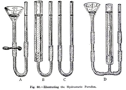
Make the experiments A, B and C, Fig. 88, one after the other.
Is the water in the small tube always at the same height as
that in the funnel or large tube?
Arrange the apparatus as in D, Fig. 88. Is the water
at the same level in all cases?
The funnel and wide tube, each contain more water than
the small tube; nevertheless, the downward pressure of the
water in each is balanced by the downward pressure of the
water in the small tube.
You have shown here that the pressure exerted by a
liquid is independent of the volume of the liquid, that is,
you have illustrated the
hydrostatic paradox.
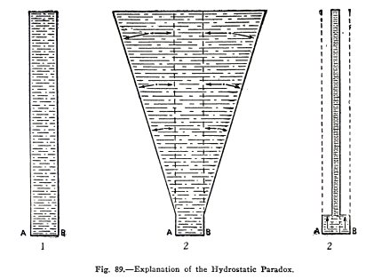
EXPLANATION OF THE HYDROSTATIC PARADOX
The hydrostatic paradox seems impossible, and that is
why it is called a paradox. It would seem to be self evident
that the greater the volume of water above a base, the greater
would be the pressure;
HYDRAULIC AND PNEUMATIC
ENGINEERING 65
and the less the volume, the less the pressure. You
have shown above, however, that the pressure on a given base
is independent of the volume of water and that it depends only
on the depth.
The paradox is explained as follows :
In 1, Fig. 89, the base AB is subject to the pressure
of the water in the cylinder above it, and in this case, the
pressure is equal to the weight of the water.
In 2, Fig. 89, the same base AB has a much larger
volume of water above it but the pressure is the same as in 1.
You will understand why, if you consider the water outside the
dotted lines. This water exerts a force perpendicular to the
sides of the cone, and another force horizontally against the
water between the dotted lines, see the arrows. Neither of
these forces has any effect downward on the base and therefore
the base is subject only to the weight of the water between
the dotted lines. This weight is the same as in 1 and
therefore the pressure on AB is the same as in 1.
In 3, Fig. 89, the base AB has a much smaller volume
above it than in either 1 or 2, but still the pressure is the
same as in 1 and 2. You will understand why from your
knowledge of Pascal's law. The water above AB is exerting
pressure downward, and according to Pascal's law this pressure
is transmitted equally and undiminished in all directions. The
pressure per square inch downward on the whole of AB,
therefore, is equal to what it would be if the whole space
between the outer dotted lines were filled with water. This
pressure is equal to that in (1) and this is why the pressure
in (3) is equal to that in (1).
HOW TO CALCULATE THE PRESSURE EXERTED BY WATER
The density (weight) of fresh water is 62 l / 2 lbs.
per cubic foot and if in (1) Fig. 89, the base AB is 1 square
foot and the height of the water is 10 feet, there are 10
cubic feet of water in the tank and the total pressure on the
bottom is 10 x 62.5 = 625 lbs.
Since the pressure exerted by water is independent of
the volume of the water and depends only on the area of the
base, the height, and the density of the water, the pressure
on AB in (2) and (3) is 625 lbs., the same as in (1).
The rule for calculating the pressure in any case is :
Pressure on any base = area of base in square feet x height of
water in feet x density of water (weight of 1 cubic foot) or,
Pressure = area x height x density.
66 HYDRAULIC AND PNEUMATIC
ENGINEERING
In the example given:
Pressure = 1 x 10 x 62.5 = 625 lbs. per square foot.
To find the pressure per square inch, first find the
pressure per square foot and then divide the result by 144,
the number of square inches in 1 square foot. For example, the
pressure on 1 square inch of AB in any of the tanks
illustrated is 625 / 144 = 4.34 lbs.
PRESSURE UNDER WATER
THE DEPTH BOMB -
TORPEDO - SUBMARINE
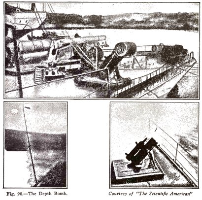
THE DEPTH BOMB
HYDRAULIC AND PNEUMATIC
ENGINEERING 67
The depth bomb is used by submarine chasers to destroy
submarines. It is a steel cylinder filled with high explosives
and equipped with a trigger which sets off the explosive at
any desired depth under water.
The trigger is released by means of a small plunger
which is exposed to the pressure of the sea water on the
outside and is supported by a spring on the inside. The
pressure of the water increases as the bomb sinks and forces
the plunger in farther against the spring, but the spring can
be so adjusted that at any desired depth the plunger releases
the trigger and the bomb explodes.
When the chaser sights a submarine it steams for it
and if it is still above water, attacks it with guns; but if
it has submerged, the chaser steams in circles around the spot
where it disappeared and drops or fires bombs adjusted to
explode at different depths.
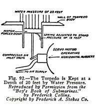
THE TORPEDO
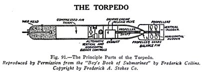
The torpedo is a cigar shaped
tube loaded in the head with high explosives which are set off
by a contact pin. It is driven by means of a compressed air
motor and is steered by horizontal and vertical rudders.
We are interested in the horizontal rudder
particularly at this point. It steers the torpedo to a depth
of 20 feet under water and keeps it at this depth. It does
this by means of the pressure of the sea water. The horizontal
rudder is controlled by a piston, Fig. 92, which is exposed to
the pressure of the sea water on the
68 HYDRAULIC AND PNEUMATIC
ENGINEERING
outside and is supported by a spring on the inside.
This piston and its spring are so adjusted that at 20 feet
under water the rudder is exactly horizontal, but at a greater
or less depth the rudder is so turned as to bring the torpedo
back to a depth of 20 feet.
THE SUBMARINE
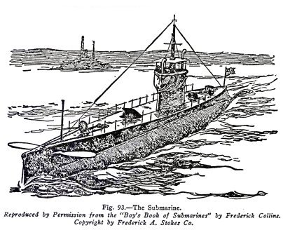
The submarine must be able to stand enormous pressures
when under water and for this reason it is made in the shape
of a cylinder with pointed ends, because this curved shape
enables it to stand greater pressure than it could if its
sides were flat; also it is made of steel because this is the
strongest material available.
You cannot experiment with the depth bomb, torpedo,
and submarine, of course, but you can make experiments to
illustrate the water pressure under which they operate. You
can show that the pressure under water increases with the
depth, that it is equal in all directions at any depth, etc.,
and this you will now do.
HYDRAULIC AND PNEUMATIC
ENGINEERING 69
EXPERIMENT No. 33
To show that the pressure under water increases with the depth
and that it is equal in all directions at any given depth.
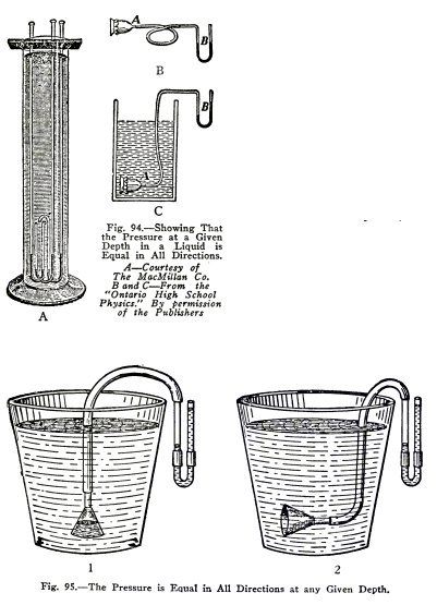
This is usually shown by means
of the apparatus A, Fig. 94. The U shaped bend of the three
tubes contain mercury to the same depth. Both ends of the
tubes are open. The short ends point upward, sidewise and
downward respectively. When the short ends of these tubes are
lowered in water, the mercury shows that the pressure
increases with the depth and is equal
in
all directions at any given depth.
70 HYDRAULIC AND PNEUMATIC
ENGINEERING
This fact is illustrated in another way by means of
the apparatus, B and C, Fig. 94. A thistle tube covered by a
sheet of rubber is placed under water and the water in the U
tube indicates a greater pressure the greater the depth. If
the thistle tube is turned in all directions at any given
depth, the water in the U tube shows that the pressure is
equal in all directions at this depth.
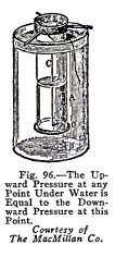
Illustrate these facts by means of the apparatus, Fig.
95.
Shove the funnel straight down (1). Does the pressure
increase with the depth?
Turn the funnel sidewise (2) and upward at any depth.
Is the pressure equal in all directions at any given depth?
EXPERIMENT No. 34
To show that water exerts
pressure upward on anything under its surface
and that the upward
pressure is equal to the downward pressure at any given
depth.
This is usually shown with the
apparatus Fig. 96. If a glass lamp chimney A, is fitted with a
thin ground glass bottom O which is held over one end by a
thread C, while this end is placed in water, it is found that
the bottom remains on when the thread is released. This shows
that water exerts pressure upward on anything under its
surface.
If now water is poured into the chimney, the bottom
HYDRAULIC AND
PNEUMATIC ENGINEERING 71
remains on until the level inside the chimney is the
same as the level outside and this is true at any depth. This
shows that the pressure upward at any depth under water is
equal to the pressure downward of the column of water inside
the chimney. In other words, it shows that the pressure upward
at any depth under water is equal to the pressure downward at
this depth.
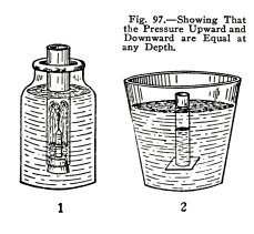
Illustrate this with the apparatus (1) Fig. 97. Put
the stoppered end in water. Is a fountain produced and does
the flow stop when the level inside is equal to that outside
the tube?
Use the apparatus (2) Fig. 97, hold the rubber sheet
on until it is under water. Does it remain?
Pour water into the tube. Does the sheet fall off when
the level inside is equal to that outside?
You have shown here that water exerts pressure upward
against anything under its surface and that the upward
pressure is equal to the downward pressure at any given depth.
HOW TO CALCULATE THE PRESSURE ON DEPTH BOMB, TORPEDO
AND SUBMARINE
Sea water is heavier than fresh water; it weighs 64
lbs. per cubic foot while fresh water weighs only 62 l / 2
lbs. per cubic foot.
DEPTH BOMB
A depth bomb is set to explode at a depth of 250 feet.
If sea water weighs 64 lbs per cubic foot, what is the
pressure per sq. in. against the plunger at this depth?
Note: Calculate
the pressure per square foot and divide this by 144, the
number of square inches in one square foot.
Area x depth x density
Pressure =
---------------------------
144
1 x
250 x 64
Pressure =
--------------------------- = 111.1 lb. per sq. in.
144
TORPEDO
A torpedo is set to travel at a depth of 15 feet under
water. What is the pressure per sq. in. on the steering
plunger at this depth?
Area x depth x density
Pressure =
---------------------------
144
1 x
15 x 64
Pressure =
--------------------------- = 6.6 lbs. per sq. in.
144
SUBMARINE
What is the pressure per square foot on the outside of
a submarine at an average depth of 150 feet in water?
Pressure =
Area x depth x density
Pressure =
1
x 150 x 64 = 9600
lbs. per sa. ft.
72 HYDRAULIC AND
PNEUMATIC ENGINEERING
BUOYANCY
WHY DOES A STEEL SHIP
FLOAT?
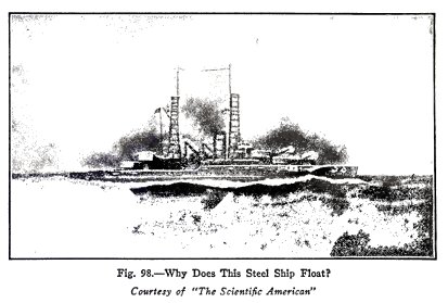
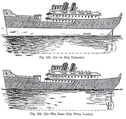
Modern ships are made of steel, example, the
superdreadnaught shown in Fig. 98, and although steel is over
seven times as heavy as water, bulk for bulk, steel ships
float. Why is this?
You know the answer, at least partly. You know that if
a ship were a solid lump of steel, it would sink. You know
also that a ship is hollow, except for its equipment, and that
this hollowness in some way enables it to float.
The true reason is that the ship as a whole is lighter
than an equal volume of water.
You will show in the following experiments that water
exerts a buoyant force on anything placed in it, and that as a
result: things which are lighter than an equal volume of water
float on water; while things which are heavier than an equal
volume of water sink but are lighter under water than above
water.
HYDRAULIC AND PNEUMATIC
ENGINEERING 73
EXPERIMENT No. 35
To illustrate the buoyant effect of water.
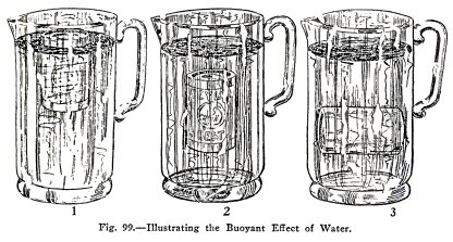
Find about your home an empty
tin can with a tight lid. Submerge it partly as in (1) and
release it. Does it shoot upward? This buoyant effect of the
water is due to the upward pressure of the water.
Submerge it entirely as in (2) and (3) and release it.
Does it shoot upward? This buoyant effect shows that the
upward pressure of the water on the under side of the can is
greater than its downward pressure on the top side.
Fill the can with water, submerge and release it. Does
it sink? Lift the full can under water and out of water. Is it
much lighter when under water? It is lighter because the water
buoys up part of its weight.
THE LAW OF ARCHIMEDES
The exact law which applies to the buoyancy of liquids
was discovered by a Greek philosopher Archimedes 200 years
before the Christian era began. It is called the law of Archimedes and it
is as follows: the buoyant
force exerted by a liquid on a body immersed in it, is exactly equal to the weight of
the liquid displaced by the body.
It is also stated more concisely as follows: a body
when placed in a liquid appears to lose weight equal to the
weight of liquid it displaces.
74 HYDRAULIC AND PNEUMATIC
ENGINEERING
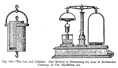
The law of Archimedes is
illustrated by means of the apparatus shown in Fig. 100. The
solid cylinder A is so made that it just fits the cup B, that
is, the cylinder has exactly the same volume as the cup.
The experiment is as follows: The cylinder A is
attached to the bottom of the cup B and both are suspended
from one pan of a balance. Weights are added to the other pan
until the cup and cylinder are just balanced.
If then, a vessel of liquid is raised up under the
cylinder A until it is completely submerged, the cup and
cylinder appear to lose weight because the liquid buoys up the
cylinder. If now the cup B is filled with the liquid, the
balance is exactly restored.
Now the weight of the liquid which fills the cup is
equal to that of the liquid displaced by the cylinder and
therefore this experiment proves the law of Archimedes,
namely, the buoyant force exerted by a liquid on a body
immersed in it is equal to the weight of the liquid displaced
by the body.
The law of Archimedes is also illustrated by means of
the apparatus shown in Fig. 101 and by means of a spring
balance, not shown.
The body is first weighed on the spring balance in
air, then in the liquid, and the apparent loss in weight in
the liquid is determined.
The vessel with the spout is then filled with the
liquid until it overflows, the body is placed in the liquid,
and the liquid displaced is weighed.
HYDRAULIC AND PNEUMATIC
ENGINEERING 75
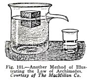
The apparent loss in weight of
the body is then compared with the weight of liquid displaced
by the body, and it is found that in every case they are
equal.
You will now make experiments
to illustrate the law of Archimedes for bodies which float on
water and for bodies which sink in water, also you will
illustrate some of the applications of this law.
 The
Science Notebook
The
Science Notebook